Wdmr and wdfr series dehumidifying dryers page 21 – AEC WD 350 through WD3000 Dehumidifying Dryers User Manual
Page 22
Advertising
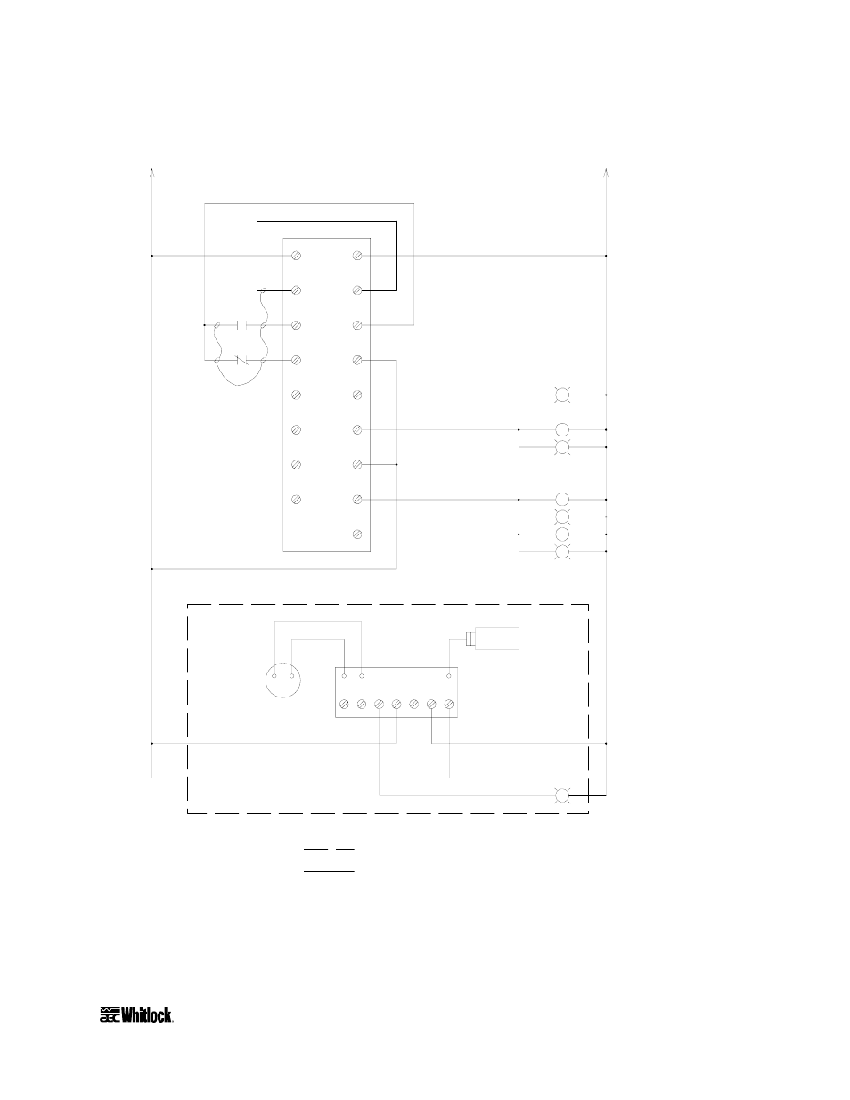
Figure 7
Typical WD25MR/FR, WD50MR/FR Electrical Schematic, Drawing 2
L1
COM
000
001
002
003
004
005
L2
-24V
COM
0
1
COM
2
3
1PLC
+24V
4
4
G
4LT
G
3LT
4
"RIGHT BED IN REGEN"
BED SHIFT RELAY
"LEFT BED IN REGEN"
"LEFT BED HEATER" ON
LEFT BED CONTACTOR
4
2
LEGEND:
OPTIONAL COMPONENTS
COMPONENTS LOCATED EXTERNALLY
OF CONTROL ENCLOSURE
4
18GA BLUE 24VDC
2
10
13
16
11
12
1CR
1M
INPUT WIRING
10
10
10
6LT
G
3C
RIGHT BED CONTACTOR
"RIGHT BED HEATER" ON
5LT
G
2C
14
15
14
15
16
1DMTR
DEW POINT
METER
-
7
6
5
4
3
2
1
4
2
1DPB
+
RED
BLK
1DPT
4
4
G
7LT
"HIGH DEW POINT"
DEW POINT CONTROL BOARD
4
2CR
2
2
2
2
2
2
2
2
2
2
OPTIONAL DEW POINT CONTROL
9
9
4
4
17
17
A0547615
Refer to your Customer Information Packet on actual drawings for your specific dryer.
WDMR and WDFR Series Dehumidifying Dryers
Page 21
Advertising