Network requirements, Configuration procedure – H3C Technologies H3C S12500-X Series Switches User Manual
Page 104
96
VRRP-Track-interface management collaboration configuration
example
In this example, the master monitors the uplink interface.
Network requirements
As shown in
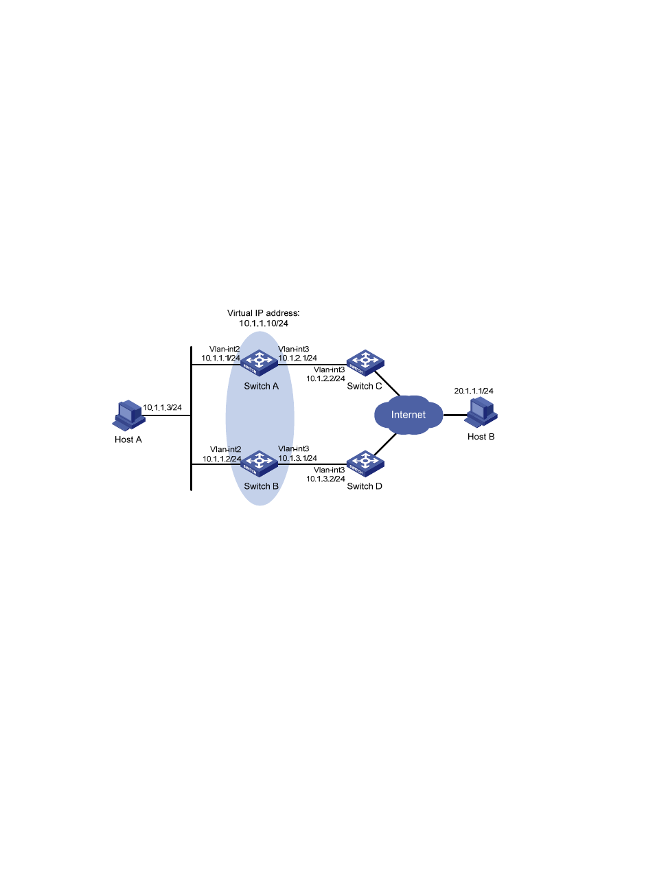
, Host A needs to access Host B on the Internet. The default gateway of Host A is
10.1.1.10/24.
Switch A and Switch B belong to VRRP group 1, whose virtual IP address is 10.1.1.10.
When Switch A works correctly, packets from Host A to Host B are forwarded through Switch A. When
VRRP detects that a fault is on the uplink interface of Switch A through the interface management module,
packets from Host A to Host B are forwarded through Switch B.
Figure 26 Network diagram
Configuration procedure
1.
Create VLANs and assign corresponding ports to them. Configure the IP address of each VLAN
interface as shown in
2.
Configure a track entry on Switch A:
# Configure track entry 1 and associate it with the link status of the uplink interface VLAN-interface
3.
[SwitchA] track 1 interface vlan-interface 3
3.
Configure VRRP on Switch A:
# Create VRRP group 1 and configure the virtual IP address 10.1.1.10 for the group.
[SwitchA] interface vlan-interface 2
[SwitchA-Vlan-interface2] vrrp vrid 1 virtual-ip 10.1.1.10
# Set the priority of Switch A in VRRP group 1 to 110.
[SwitchA-Vlan-interface2] vrrp vrid 1 priority 110
# Configure to monitor track entry 1, and specify the priority decrement as 30.
[SwitchA-Vlan-interface2] vrrp vrid 1 track 1 reduced 30
4.
Configure VRRP on Switch B:
<SwitchB> system-view