Configuration procedure – H3C Technologies H3C S12500-X Series Switches User Manual
Page 62
54
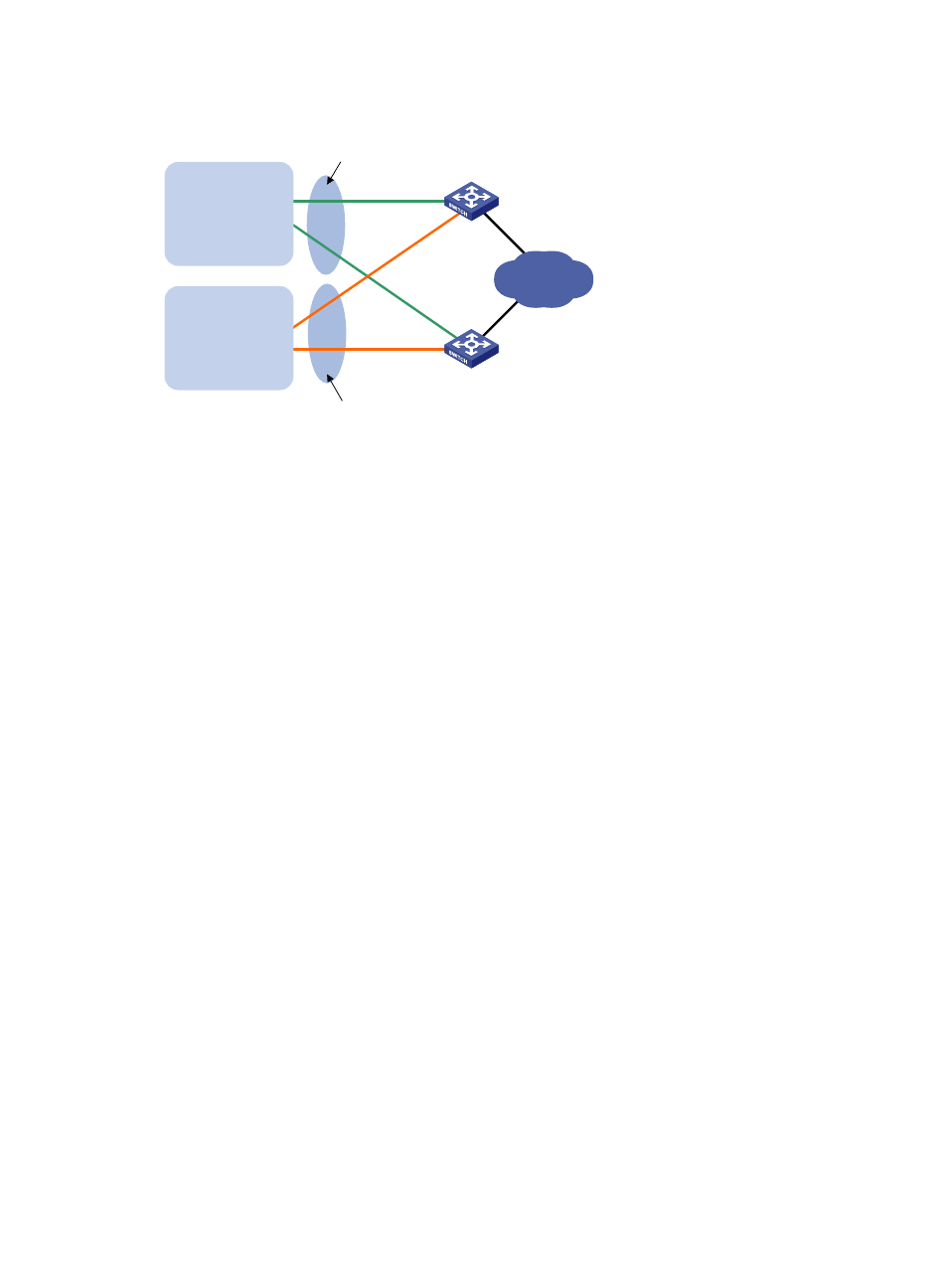
Figure 17 Network diagram
Configuration procedure
1.
Configure Switch A:
# Configure VLAN 2.
<SwitchA> system-view
[SwitchA] vlan 2
[SwitchA-vlan2] port ten-gigabitethernet 1/0/5
[SwitchA-vlan2] quit
[SwitchA] interface vlan-interface 2
[SwitchA-Vlan-interface2] ip address 10.1.1.1 255.255.255.128
# Create VRRP group 1, and set its virtual IP address to 10.1.1.100.
[SwitchA-Vlan-interface2] vrrp vrid 1 virtual-ip 10.1.1.100
# Assign Switch A a higher priority than Switch B in VRRP group 1, so Switch A can become the
master in the group.
[SwitchA-Vlan-interface2] vrrp vrid 1 priority 110
[SwitchA-Vlan-interface2] quit
# Configure VLAN 3.
[SwitchA] vlan 3
[SwitchA-vlan3] port ten-gigabitethernet 1/0/6
[SwitchA-vlan3] quit
[SwitchA] interface vlan-interface 3
[SwitchA-Vlan-interface3] ip address 10.1.1.130 255.255.255.128
# Create VRRP group 2, and set its virtual IP address to 10.1.1.200.
[SwitchA-Vlan-interface3] vrrp vrid 2 virtual-ip 10.1.1.200
2.
Configure Switch B:
# Configure VLAN 2.
<SwitchB> system-view
[SwitchB] vlan 2
[SwitchB-vlan2] port ten-gigabitethernet 1/0/5
[SwitchB-vlan2] quit
[SwitchB] interface vlan-interface 2
Switch A
Switch B
Virtual IP address 1:
10.1.1.100/25
Virtual IP address 2:
10.1.1.200/25
XGE1/0/5
Vlan-int2
10.1.1.1/25
XGE1/0/5
Vlan-int2
10.1.1.2/25
Internet
VLAN 2
Gateway:
10.1.1.100/25
VLAN 3
Gateway:
10.1.1.200/25
XGE1/0/6
Vlan-int3
10.1.1.130/25
XGE1/0/6
Vlan-int3
10.1.1.131/25