Configuration procedure – H3C Technologies H3C S12500-X Series Switches User Manual
Page 93
85
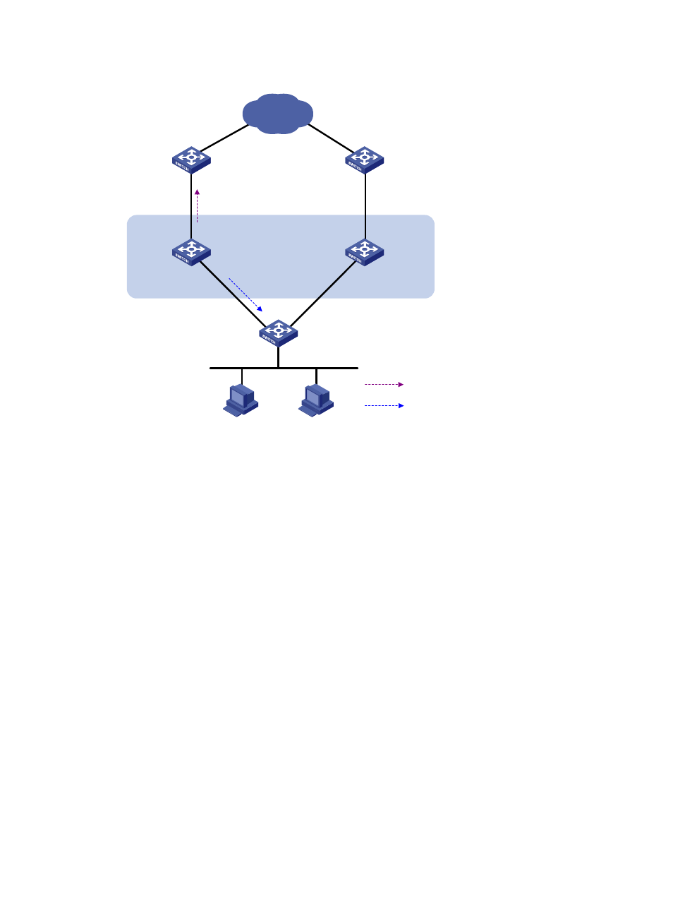
Figure 23 Network diagram
Configuration procedure
1.
Create VLANs and assign corresponding ports to them. Configure the IP address of each VLAN
interface as shown in
2.
On Switch A, configure the source address of BFD echo packets as 10.10.10.10.
<SwitchA> system-view
[SwitchA] bfd echo-source-ip 10.10.10.10
3.
On Switch A, create track entry 1 to be associated with the BFD session to check whether the uplink
device with the IP address 1.1.1.2 is reachable.
[SwitchA] track 1 bfd echo interface vlan-interface 3 remote ip 1.1.1.2 local ip
1.1.1.1
4.
On Switch A, create VRRP group 1, and configure the virtual IP address of the group as
192.168.0.10. Configure the priority of Switch A in VRRP group 1 as 110. Configure VRRP group
1 to monitor the status of track entry 1. When the status of the track entry becomes Negative, the
priority of Switch A decreases by 20.
[SwitchA] interface vlan-interface 2
[SwitchA-Vlan-interface2] vrrp vrid 1 virtual-ip 192.168.0.10
[SwitchA-Vlan-interface2] vrrp vrid 1 priority 110
[SwitchA-Vlan-interface2] vrrp vrid 1 track 1 reduced 20
[SwitchA-Vlan-interface2] return
5.
On Switch B, create VRRP group 1, and configure the virtual IP address of the group as
192.168.0.10.
<SwitchB> system-view
[SwitchB] interface vlan-interface 2
[SwitchB-Vlan-interface2] vrrp vrid 1 virtual-ip 192.168.0.10
Internet
Master
uplink device
Backup
uplink device
Uplink
Virtual router
Virtual IP address:
192.168.0.10
Vlan-int2
192.168.0.101/24
Vlan-int2
192.168.0.102/24
Switch A
Master
Switch B
Backup
Vlan-int3
1.1.1.1/24
Vlan-int3
1.1.1.2/24
L2 switch
Uplink
VRRP packets
BFD probe packets