Fspf configuration example, Network requirements, Configuration procedure – H3C Technologies H3C S12500-X Series Switches User Manual
Page 84: Creating a vsan
75
# Display the FC routing table in VSAN 1 on Switch C.
[SwitchC] display fc routing-table vsan 1
Routing Table: VSAN 1
Destinations : 6 Routes : 6
Destination/mask Protocol Preference Cost Interface
0x010000/8 STATIC 10 0 Vfc2
0x020000/8 STATIC 10 0 Vfc2
0xfffc03/24 DIRECT 0 0 InLoop0
0xfffffa/24 DIRECT 0 0 InLoop0
0xfffffc/24 DIRECT 0 0 InLoop0
0xfffffd/24 DIRECT 0 0 InLoop0
# On Switch A, use the fcping command to ping Switch C and check whether Switch C is reachable.
[SwitchA] fcping fcid fffc03 vsan 1
FCPING fcid 0xfffc03: 128 data bytes, press CTRL_C to break
Reply from 0xfffc03: bytes = 128 time = 23 ms
Reply from 0xfffc03: bytes = 128 time = 9 ms
Reply from 0xfffc03: bytes = 128 time = 19 ms
Reply from 0xfffc03: bytes = 128 time = 14 ms
Reply from 0xfffc03: bytes = 128 time = 25 ms
--- 0xfffc03 fcping statistics ---
5 packet(s) transmitted
5 packet(s) received
0.00% packet loss
round-trip min/avg/max = 9/18/25 ms
The output shows that Switch A can reach Switch C.
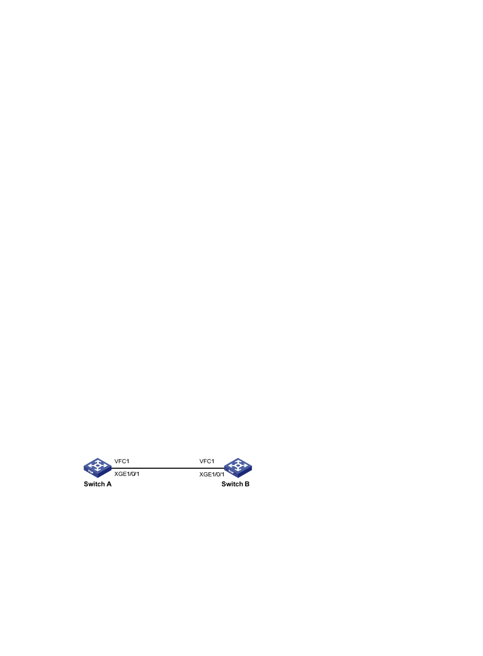
FSPF configuration example
Network requirements
As shown in
, configure FSPF to enable the two FCF switches to communicate with each other.
Figure 23 Network diagram
Configuration procedure
1.
Configure Switch A:
# Configure Switch A to operate in advanced mode, save the configuration, and reboot Switch A.
(Skip this step if the switch is operating in advanced mode.)
<SwitchA> system-view
[SwitchA] system-working-mode advance