Configuration procedure – H3C Technologies H3C S12500-X Series Switches User Manual
Page 75
68
•
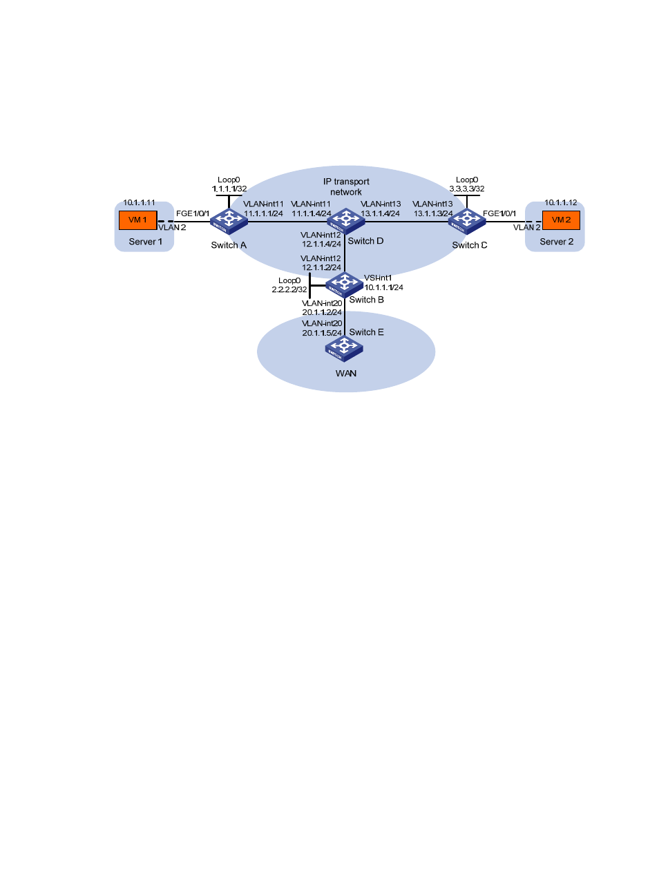
Configure VXLAN 10 on Switch A through Switch C to provide connectivity for the VMs across the
network sites.
•
Manually establish VXLAN tunnels and assign the tunnels to VXLAN 10.
•
Configure a centralized VXLAN IP gateway on Switch B for VXLAN 10 to access the WAN.
Figure 17 Network diagram
Configuration procedure
1.
Configure IP addresses and unicast routing settings:
# Assign IP addresses to interfaces, as shown in
. (Details not shown.)
# Configure OSPF on all transport network switches (Switches A through D). (Details not shown.)
# Configure OSPF to advertise routes to networks 10.1.1.0/24 and 20.1.1.0/24 on Switch B
and Switch E. (Details not shown.)
2.
Configure Switch A:
# Enable L2VPN.
<SwitchA> system-view
[SwitchA] l2vpn enable
# Enable Layer 2 forwarding for VXLANs.
[SwitchA] undo vxlan ip-forwarding
# Create the VSI vpna and VXLAN 10.
[SwitchA] vsi vpna
[SwitchA-vsi-vpna] vxlan 10
[SwitchA-vsi-vpna-vxlan10] quit
[SwitchA-vsi-vpna] quit
# Assign an IP address to Loopback 0. The IP address will be used as the source IP address of the
VXLAN tunnels to Switch B and Switch C.
[SwitchA] interface loopback0
[SwitchA-Loopback0] ip address 1.1.1.1 255.255.255.255
[SwitchA-Loopback0] quit
# Create a VXLAN tunnel to Switch B. The tunnel interface name is Tunnel 1.
[SwitchA] interface tunnel 1 mode vxlan