Network requirements, Configuration procedure – H3C Technologies H3C S12500-X Series Switches User Manual
Page 80
73
# Verify that VM 1, VM 2, and VLAN-interface 20 (20.1.1.5) on Switch E can ping each other.
(Details not shown.)
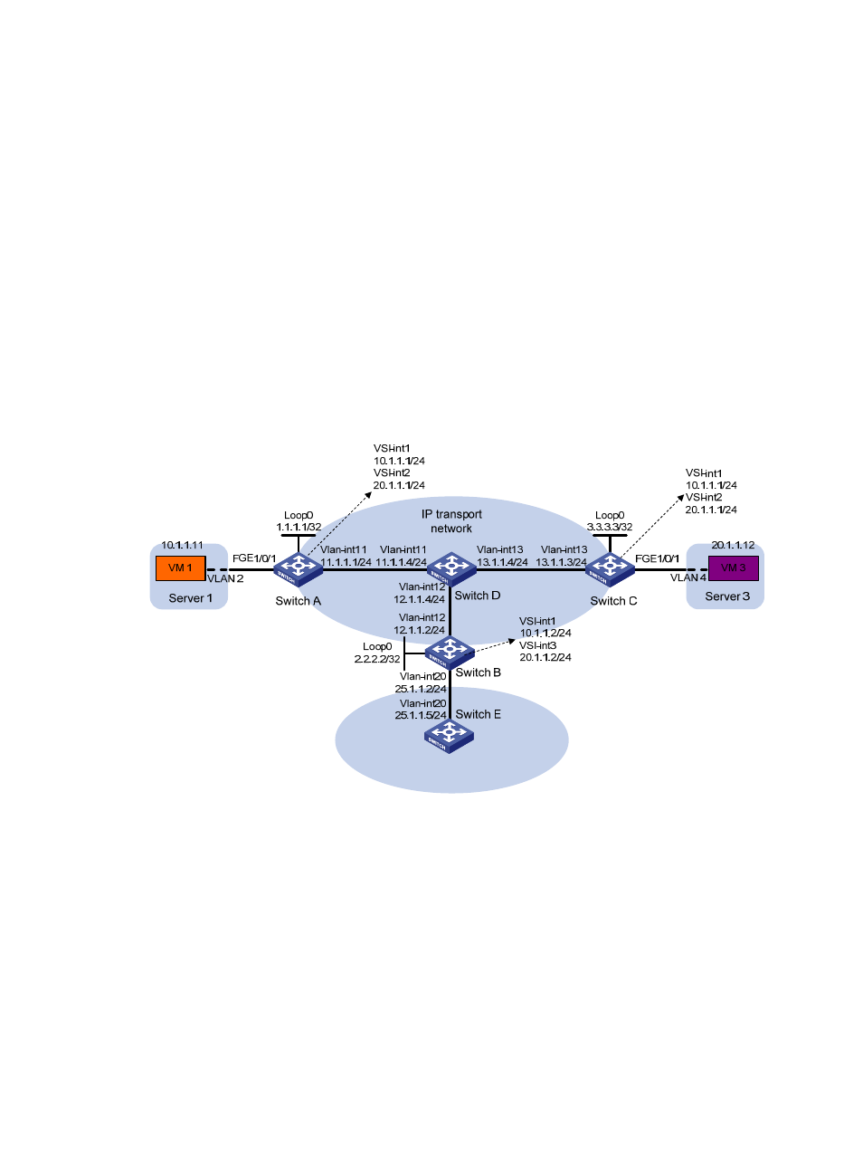
Distributed VXLAN IPv4 gateway configuration example
Network requirements
As shown in
:
•
Configure VXLAN 10 and VXLAN 30 as unicast-mode VXLANs on Switch A, Switch B, and Switch
C to provide connectivity for the VMs across the network sites.
•
Manually establish VXLAN tunnels and assign the tunnels to the VXLANs.
•
Configure distributed VXLAN IP gateways on Switch A and Switch C to forward traffic between
VXLAN 10 and VXLAN 30.
•
Configure Switch B as a border gateway to forward traffic between the VXLANs and the WAN
connected to Switch E.
Figure 18 Network diagram
Configuration procedure
1.
Configure IP addresses and unicast routing settings:
# Assign IP addresses to interfaces, as shown in
. (Details not shown.)
# Configure OSPF on all transport network switches (Switches A through D). (Details not shown.)
# Configure OSPF to advertise routes to networks 10.1.1.0/24, 20.1.1.0/24, and 25.1.1.0/24
on Switch B and Switch E. (Details not shown.)
2.
Configure Switch A:
# Enable L2VPN.
<SwitchA> system-view
[SwitchA] l2vpn enable