H3C Technologies H3C WX5000 Series Access Controllers User Manual
Page 14
1-8
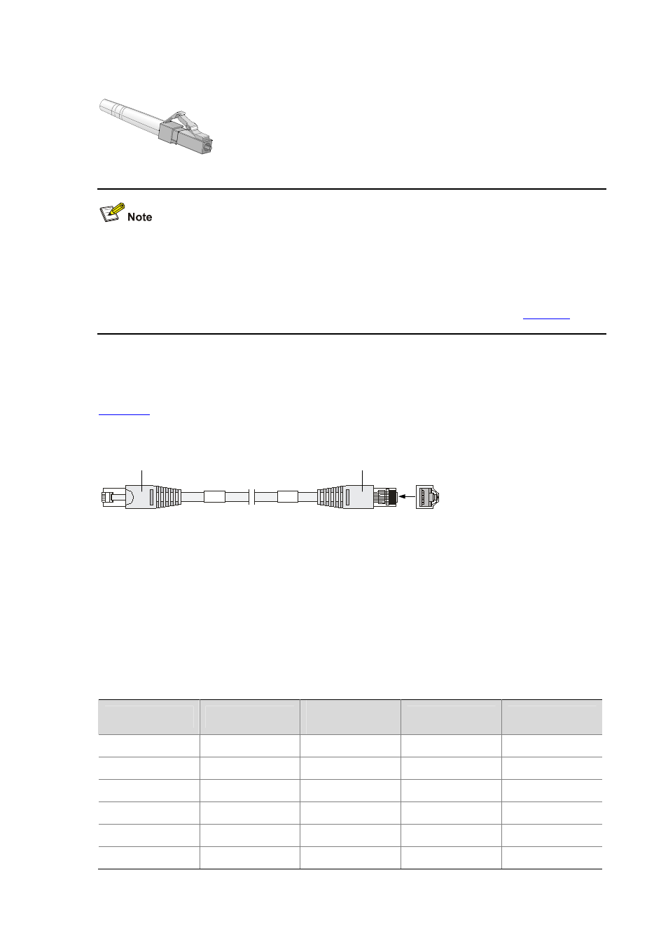
The Ethernet optical interfaces of the WX5002V2 support LC connectors only.
Figure 1-7
LC connector
z
Before using an optical fiber to connect a network device, make sure that the optical fiber connector
matches the optical module.
z
Before connecting the fiber, make sure that the receiving-end optical power does not exceed the
upper threshold of the receiving optical power. Excessive receiving optical power is very likely to
burn the optical module. For optical power values of the optical modules, refer to
.
5) Ethernet electrical interface cables
Usually, you can use a category-5 twisted pair cable to connect an electrical interface to an Ethernet.
shows an Ethernet cable.
Figure 1-8
Ethernet cable
RJ45
Connector
A
A
1
8
RJ45
Connector
Ethernet cables fall into the following two categories:
z
Standard cable: Also called straight-through cable. At both ends of a standard cable, wires are
crimped in the RJ-45 connectors in the same sequence. A straight-through cable is used to
connect a terminal (for example, PC or router) to a Hub or LAN Switch.
z
Crossover cable: At both ends of a crossover cable, wires are crimped in the RJ-45 connectors in
different sequences. A crossover cable is used to connect a terminal (for example, a PC or router)
to another terminal. You can make crossover cables by yourself as needed.
Table 1-10
Straight-through cable pinouts
RJ-45
Signal
Category-5
twisted pair
Signal direction
RJ-45
1 TX+
White
(Orange)
Æ
1
2 TX-
Orange
Æ
2
3 RX+
White
(Green)
Å
3
4 — Blue
— 4
5 — White
(Blue)
— 5
6 RX-
Green
Å
6