Grass Valley Kaleido-MX (1RU) v.7.80 User Manual
Page 26
12
Installation
System Control
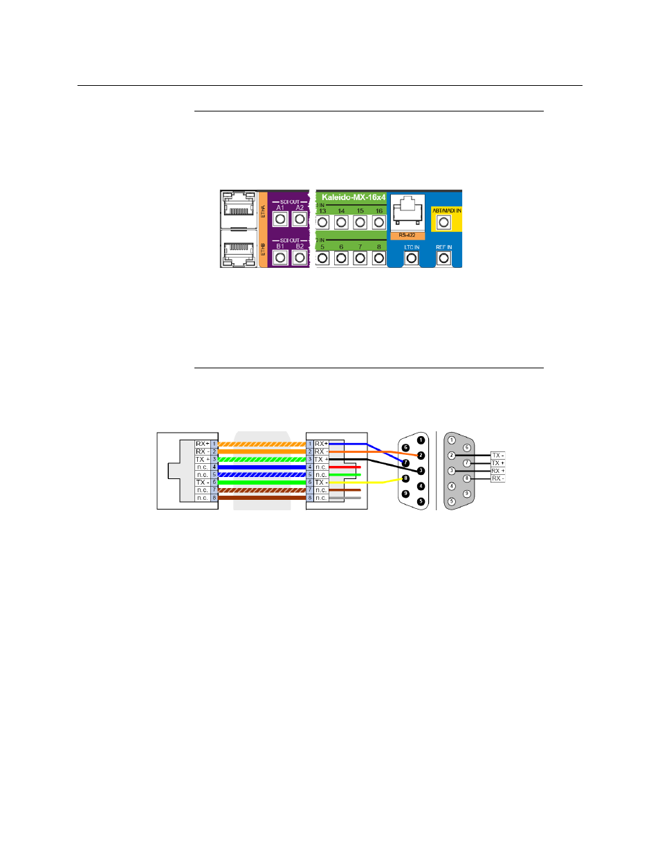
RS-422 connection diagram
The pinout for the RS-422 signals on the RJ-45 connectors, and the wiring diagrams for the
appropriate adapters, are shown here:
Standard wiring between multiviewer and devices wired to SMPTE “slave” specification (e.g. most
routers, Ross Synergy switchers, Nevion ETH-CON)
Notes
• In the case of the Kaleido-MX (1RU) 16 × 4 model, there are two Ethernet
connectors, labelled ETHA (for Output A), and ETHB (for Output B). The RS-
422 port is located at the other end of the rear panel, next to the input
module connectors.
System control connectors on Kaleido-MX (1RU) 16 × 4
• The Kaleido-MX multiviewers’ RS-422 ports have an RJ-45 connector in
order to preserve space on a busy panel. The RS-422 interface specifies a
DE-9 connector, so if you are using this interface, you will require a DE-9-
to-RJ-45 adapter. Grass Valley supplies two adapter models, correctly
wired for this application: a straight adapter (part no. 1737-3000-102), and
a crossover adapter (part no. 1792-3700-100).
Pinout of an RS-422
port’s RJ-45 connector
on the multiviewer
Pinout of straight adapter (Grass
Valley part no. 1737-3000-102)
RJ-45
DE-9 male DE-9 female
Pinout of RS-422
connector on SMPTE
slave device