Grass Valley Kaleido-MX (1RU) v.7.80 User Manual
Page 27
13
Kaleido-MX (1RU)
Hardware Description & Installation Manual
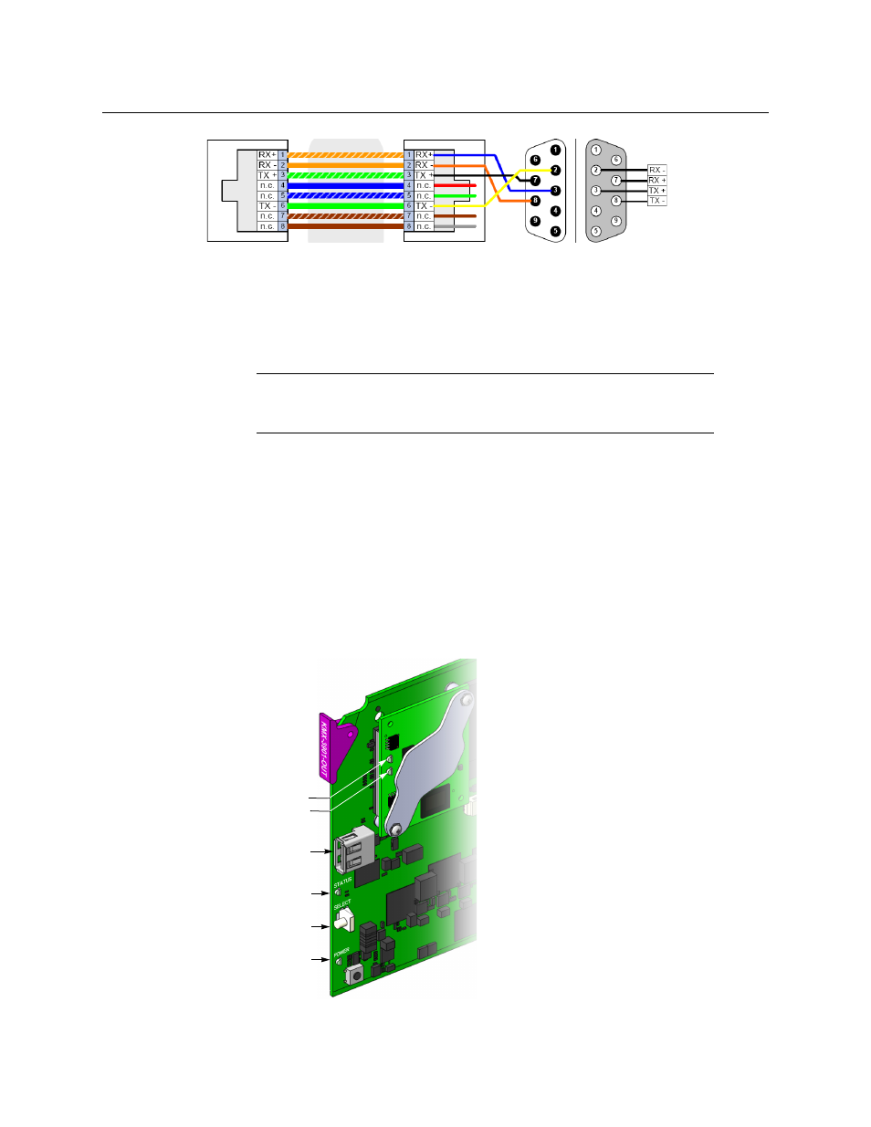
Standard wiring between multiviewer and devices wired to SMPTE “master” specification (e.g. Philips
Jupiter router control system, Grass Valley Presmaster PCS)
For more information about the serial ports’ specifications, see
page 39. For more information about the RS-422 serial connections, see the “Serial
Connections” section in the Routers chapter of the Kaleido-X User’s Manual.
KMX-3901-OUT front card-edge USB connector
Every output module also has one USB connector, into which you may connect a mouse,
keyboard, or USB flash memory for a software upgrade or data backup. The diagram below
shows the USB connector, between various LED indicators and the Select button, on the
output cards’ front edge. See
Kaleido-MX Output Card Interface
on page 24, for a detailed
description of the LED indicators, and
Using the Densité Frame Control Panel
for more information on the Select button.
Note:
The two RS-422 ports on the multiviewer side have no ground pin.
Using the appropriate DE-9S-to-RJ-45 adapter, an external device should be
able to communicate with a multiviewer despite the lack of a ground.
Pinout of an RS-422
port’s RJ-45 connector
on the multiviewer
RJ-45
DE-9 male DE-9 female
Pinout of crossover adapter (Grass
Valley part no. 1792-3700-100)
Pinout of RS-422
connector on SMPTE
master device
Status LED
Select button
Power LED
Output card
(bottom)
USB connector
Heartbeat LED
SD card access LED
Other side:
ETH com LED
(future use)
CPU 0 LED (not used)
CPU 1 LED