Grass Valley Maestro Master Control v.2.4.0 User Manual
Page 125
121
MAESTRO User Manual
Section 2 — The Maestro Configuration Editor
inputs do not necessarily need to be connected to Maestro outputs
although many of them will be Maestro-related as in the examples below.
A separate table must be created for each channel (that is, for each Maestro
Processor). Each table is given a name and assigned to a channel using the
Channel Setup table. The figures below represent two monitor follow
tables, one named SD-MonFllw which will be assigned to the channel
“WXYZ-SD” and another named HD-MonFllw which will be assigned to
the channel “WXYZ-HD.”
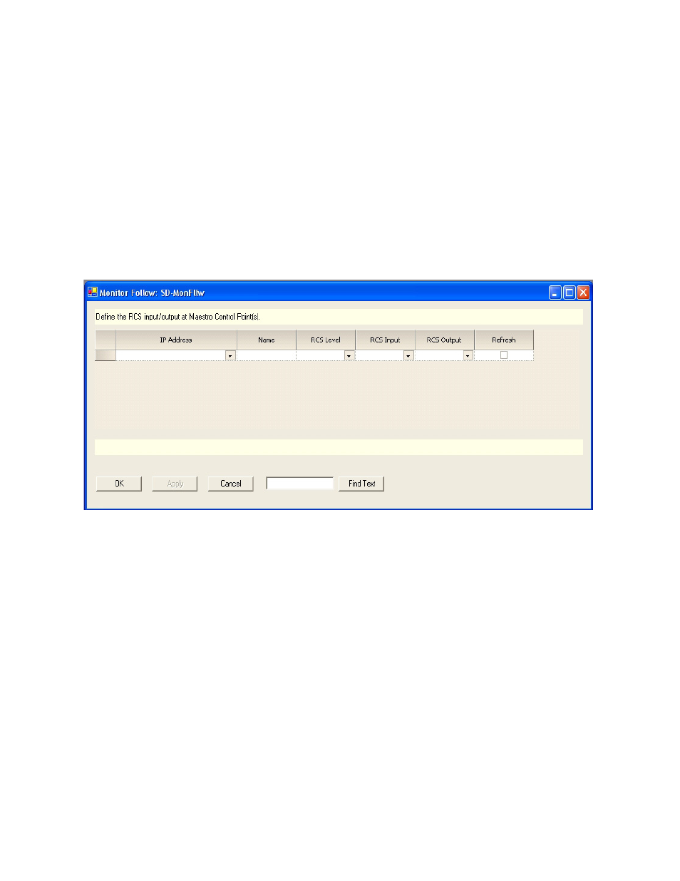
shows a new Monitor Follow table. An explanation of the table
entries appears below the table.
Figure 64. Monitor Follow Table
IP Address
The IP address of the control panel (hardware control panel or GUI PC
panel server card) from which channel delegation operations may be per-
formed which should cause monitor follow router switches. The source for
the available selections is the Network Description table.
Name
A user-specified name for a router input/router output pair to be switched
when a channel delegation operation is performed. Some examples are
PGM, PST, Off-air Return, etc. Any name is valid but it should describe the
source being directed to the monitors.
RCS Level
This is the Router Control System (RCS) Level that contains the router
inputs and outputs. The inputs and outputs will be switched when a
channel delegation operation is performed from the device at the specified