Network description – Grass Valley Maestro Master Control Installation v.2.4.0 User Manual
Page 146
146
MAESTRO Installation and Service Manual
Section 5 — The Maestro Configuration Editor
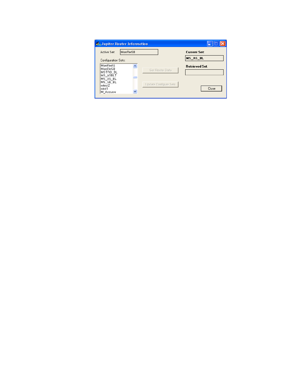
Figure 70. Jupiter Router Information (Example)
Note
On the Connect to Server menu, the “Active” set field indicates the active set
on the Jupiter system. “Current Set” refers to the active Jupiter configuration
file that is being used with the Maestro configuration currently being edited.
When finished, Click the
Apply
button, and then the
OK
button to save.
Note
After all the configuration tables are edited and saved you must “compile” the
set before it can be downloaded using the Deployment Control Center. This
process is described in
.
Network Description
This screen has a table that is used to enter the facility and control LAN IP
addresses for each Maestro channel and control panel.
In some cases, these entries will vary. For example:
•
If no hardware control panel is present, addresses must be entered for
the GUI (actually, the addresses will apply to a PCI Panel Server board,
which acts as an interface between the GUI and the Processor). In these
systems, the PCI Panel Server is typically installed in the GUI PC.
•
If this is a multi-channel system, and the GUI will be used to control a
channel independently from any hardware control panel, then a dedi-
cated PCI Panel Server board must be present on the network to service
the GUI. The address of the PCI Panel Server would then be added to
this table. If there are multiple GUIs, and they will be used to control
channels independently, each must be served by a dedicated PCI Panel
Server board.