Figure 107, Figure 108 – Grass Valley Maestro Master Control Installation v.2.4.0 User Manual
Page 199
MAESTRO Installation and Service Manual
199
5th Step: Input/Output Sets
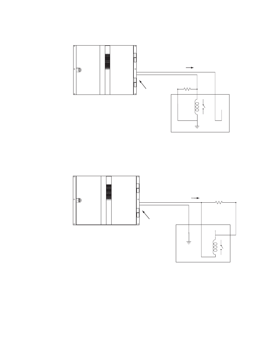
Figure 107. GPO Connections to External Controlled Device (Example1)
Figure 108. GPO Connections to External Controlled Device (Example 2)
Maestro
GPO Port/Relay
See Notes
1A
1B
Note 1
Connections between Maestro
GPIO Connector and controlled
external device are bipolar.
Note 2
Maximum current through Maestro relay = 250 mA
Maximum voltage for relay = 10 V
"Transition in Progress" signal
Controlled external device
+5 V
220 ohm
1/8 W
resistor