Managing partitions and signal types – Grass Valley UniConfi NVISION Series v.1.3 User Manual
Page 65
UniConfig Configuration Application • User’s Guide
53
8. Managing Partitions and Signal Types
Setting Up Partitions
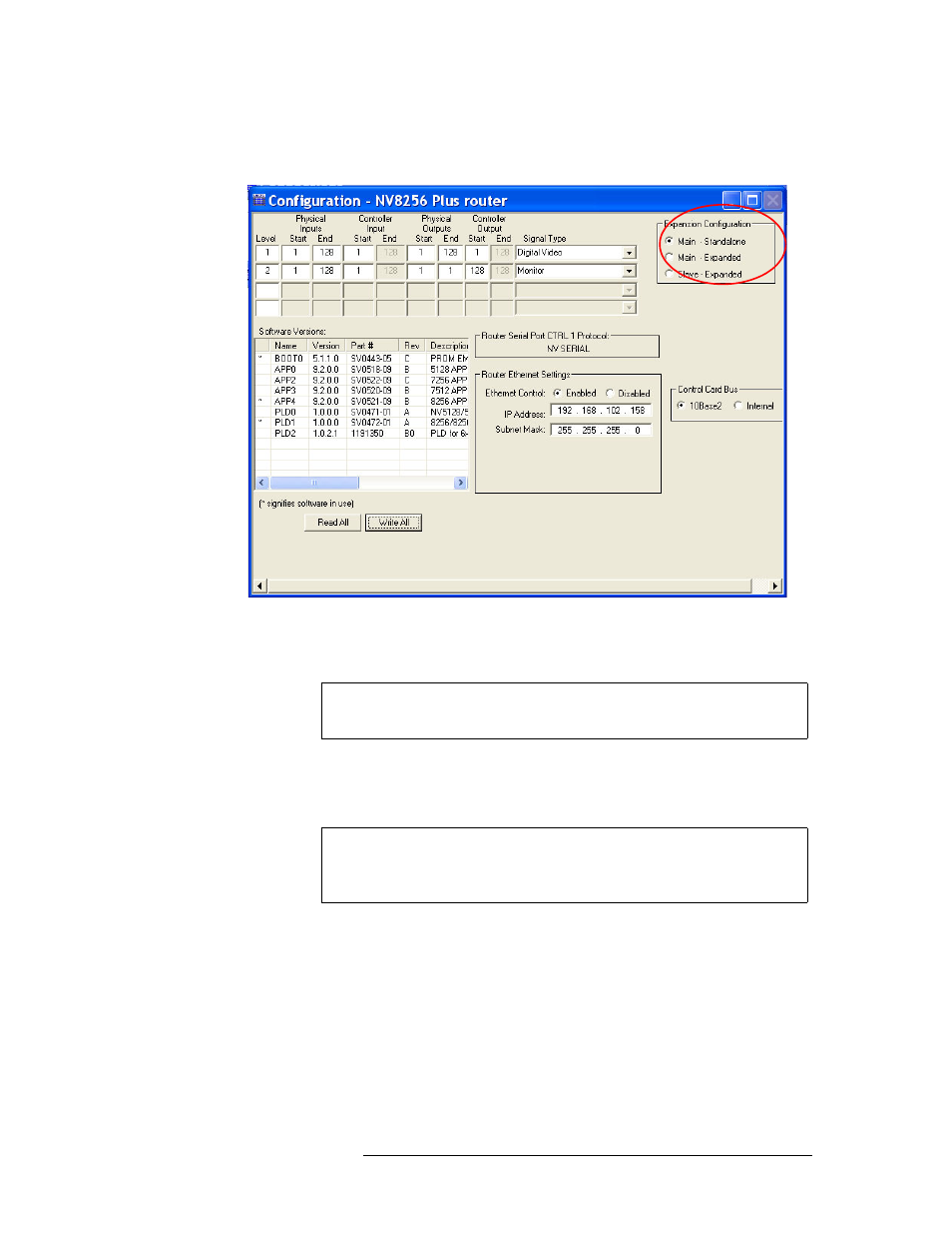
matrix. The ‘Configuration’ window for these routers displays an additional ‘Expansion’ sec-
tion:
Figure 8-2. Example of a Configuration Window for a Router with Frame Expansion
5 Click
Read All
. The ‘Configuration’ window populates with the current router configuration and
Ethernet settings. If no prior configuration is stored, many of the fields are blank.
6 To set up a partition, enter ‘Level’, ‘Physical Inputs’, ‘Controller Inputs’, ‘Physical Outputs’
and ‘Controller Output’ information for each switching matrix in the fields provided. Each row
represents one partition (called ‘Level’ on the interface) in the router control system.
For the NV5100MC and NV5128, there are 8 partitions. Only four display at any one time.
Click
Partition 1–4
or
Partition 5–8
to view the corresponding levels. For all other routers, there
are four partitions. Machine control cards and corresponding signals must be assigned to a sin-
gle, individual partition; the physical inputs and outputs must be on a separate level from other
signal types. The physical input and output ranges should be 1–32 or 1–64, depending on the
size of your machine control partition.
Note
Make sure that the ‘Main - Standalone’ radio button is selected in the
‘Expansion’ section.
Note
Partitions (also called ‘levels’) must be unique. If a partition is not unique,
the router control system has no way of distinguishing one set of cross-
points from another.