Managing partitions and signal types – Grass Valley UniConfi NVISION Series v.1.3 User Manual
Page 74
62
Rev 1.1 • 14 Dec 09
8. Managing Partitions and Signal Types
Setting Up Partitions
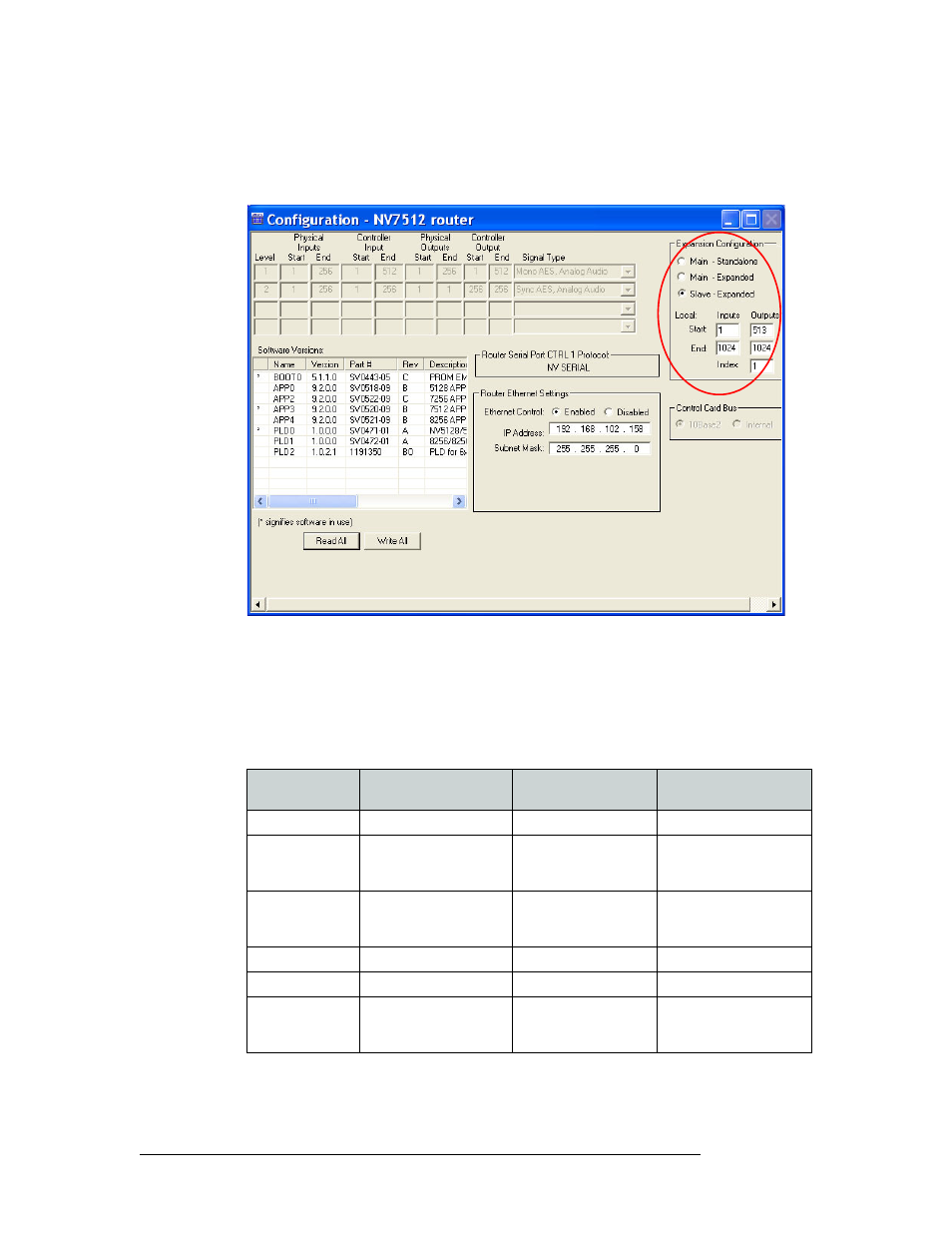
5 Select the ‘Slave - Expanded’ radio button in the ‘Expansion’ section. This sets the control card
on the router as the slave control card controlled by the master (or main) router and expands the
‘Expansion’ section:
Figure 8-6. Example of a Configuration Window for Routers with Frame Expansion Section
6 For ‘Local Inputs’ and ‘Outputs’, enter a ‘Start’ and ‘End’ number in the corresponding fields.
The inputs are the total number of signals for all routers. In this example, the NV7512 can man-
age 512×512 and is connected to a second 512×512 router. This means that the router receives a
total of 1,024 inputs: 512 from the local inputs and 512 from the connected router.
This table lists the maximum number of inputs and outputs for the slave router for each router:
Router
Number of Frames That
Can be Connected
Inputs
Outputs
NV5256
2 at 256 ports each
2 routers: 1–512
257–512
NV7256-Plus
4 at 256 x 256 each
2 routers: 1–512
3 routers: 1–768
4 routers: 1–1,024
2nd router: 257–512
3rd router: 513–768
4th router: 769–1,024
NV7512
4 at 512 x 512 each
2 routers: 1–1,024
3 routers: 1–1,536
4 routers: 1–2,048
2nd router: 513– 1,024
3rd router: 1,025–1,536
4th router: 1,537–2,048
NV8256-Plus
2 at 256 x 256
2 routers: 1–512
257–512
NV8288-Plus
2 at 288 x 288
2 routers: 1–576
289–576
NV8500 Family:
NV8280-Plus
NV8576-Plus
2 at 288 x 288
2 at 576 x 576
2 routers: 1–576
2 routers: 1–1,152
288– 576
576–1,152