4 connecting encoders – HEIDENHAIN PWM 20 User Manual
Page 22
Operating Instructions
en
PWM 20
24
4.4
Connecting encoders
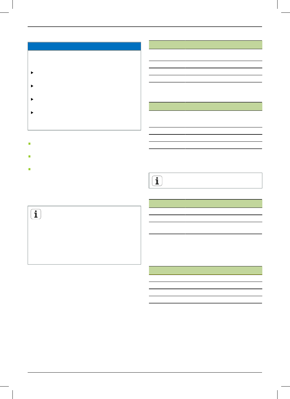
NOTICE
Danger of damage to the device and encoder damage
due to incorrect voltage supply range and incorrect
wiring!
Note the voltage supply range of the connected
encoder.
Check whether the cable between the encoder and
device is correctly wired.
The cable between the encoder and the device must
not be connected or disconnected while under power.
The connection and operation of the device with
encoders that are not from HEIDENHAIN is the user‘s
own risk.
Connections
Encoders with a 15-pin interface are connected to
encoder input X1 on the front panel.
When connected to the control loop, encoder output X2
is used for encoders with a 15-pin interface.
Encoders with 8+2-pin DRIVE-CLiQ interfaces are
connected to encoder input X4 on the front panel.
For information on the location of the connections, see
"Product overview", page 23.
The pin layouts of the connecting cables are described in
the catalog.
Notes on the signal assignment of the pins in the
annex:
Cable shield connected to housing;
U
P
= Power supply
Sensor: The sensor lines are connected
internally with the corresponding voltage
supply, depending on the settings in the
ATS software ("ATS Software Operating
Instructions" document, see "Notes on reading
the documentation", page 18).
EnDat/SSI interface
Pin
Function
1, 3, 7, 9, 11, 14
Incremental signals (only with ordering
designations EnDat 01 and EnDat 02)
2, 4, 10, 12
Voltage supply
5, 8, 13, 15
Position values
6
Internal shield
For signal assignment of EnDat/SSI, see "F".
Fanuc, Mitsubishi, Yaskawa, or Panasonic interface
Pin
Function
1, 3, 7, 9, 11, 14
Incremental signals (if available, only
for adjusting; do not use in normal ope-
ration)
2, 4, 10, 12
Voltage supply
5, 8, 13, 15
Position values
6
/
For signal assignment of Fanuc, see "G".
For signal assignment of Mitsubishi, see "H".
For signal assignment of Yaskawa and Panasonic, see "I".
Fanuc and Mitsubishi: Do not use pins 5 and 13
for one-pair transmission.
1 V
pp
/ 3 V
pp
interface
Pin
Function
1, 3, 7, 9, 11, 14
Incremental signals
2, 4, 10, 12
Voltage supply
5, 6, 8, 13, 15
Other device-dependent signals
(switched internally)
For signal assignment of 1 V
pp
with limit positions, see "J".
For signal assignment of 1 V
pp
/Z1, see "K".
For signal assignment of 1 V
pp
with clock/data, see "L".
11 µA
pp
/ 25 µA
pp
interface
Pin
Function
1, 3, 7, 9, 11, 14
Incremental signals
2, 4
Voltage supply
5, 6, 8, 10, 12, 13, 15
/
6
Internal shield
For signal assignment of 11 µA
pp
(25 µA
pp
), see "M".