HEIDENHAIN PWM 20 User Manual
Page 23
PWM 20
Operating Instructions
en
25
TTL interface (with limit positions) and HTL interface
Pin
Function
1, 3, 7, 9, 11, 14
Incremental signals
2, 4, 10, 12
Voltage supply
3, 13, 15
/
6, 8
Limit signals
(if supported by the encoder)
For signal assignment of TTL and HTL, see "N".
Connection X4
For signal assignment of DRIVE-CLiQ, see "P".
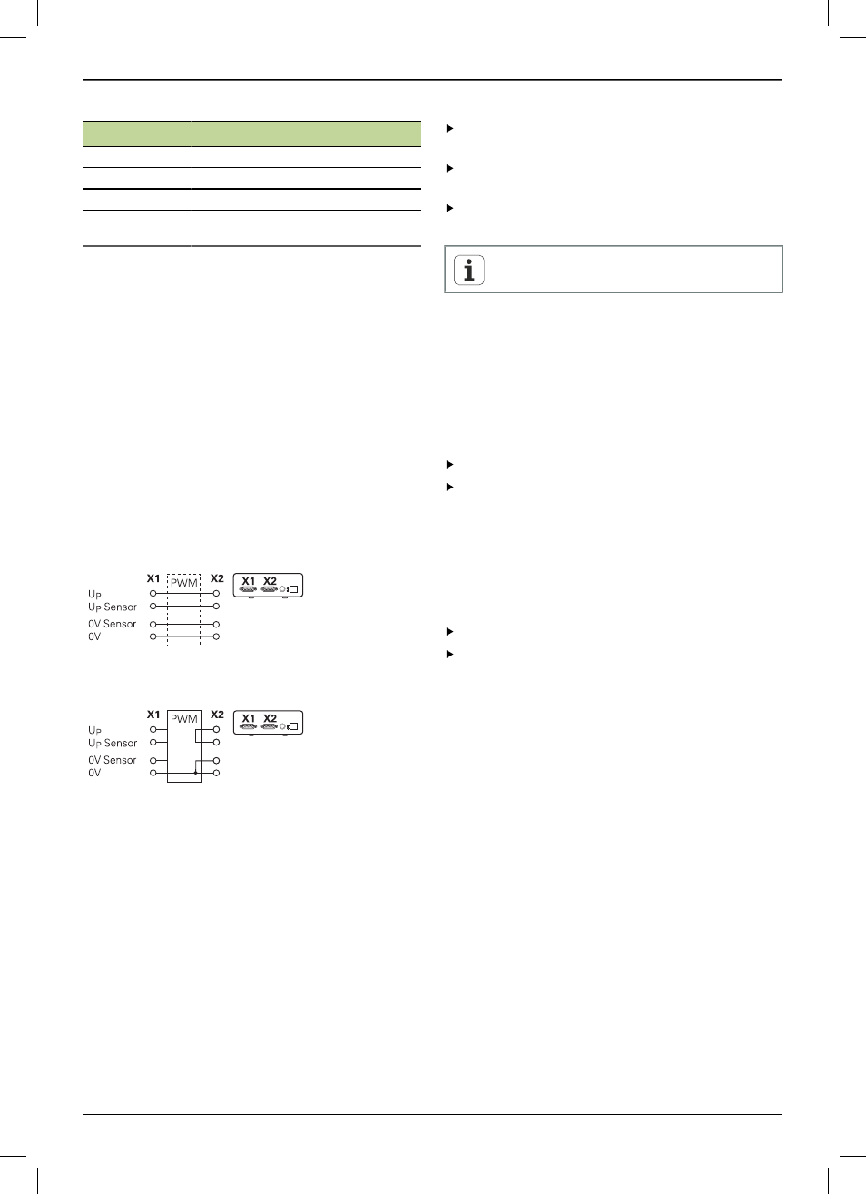
Encoder output X2
The encoder input X1 of the device is electrically connected
with the encoder output X2. The signals and the pin layout
at the output correspond to the respective signals at the
input (signals are picked off or actively emulated).
There is no galvanic isolation of the signals. The supply and
sensor lines are switched via the ATS software as of version
V2.6 depending on the respective mode of operation and
may be connected (see examples below). It is always
ensured that the supply voltage generated by the device is
not present at X2.
Example 1
– Device in feed-through mode (the encoder is
powered by the subsequent electronics) / ATS software not
started.
Example 2
– The device powers the encoder via X1:
Connecting the encoder cables
Connect the cables of the encoders tightly to the
respective connections.
If the cable connectors include mounting screws, do not
overtighten them.
Do not subject the plug connections (encoder input X4)
to mechanical load.
Vacant pins or wires must not be used.
4.4.1
Grounding conditions when connected to the
control loop
The device has an internal wide-range switching power
supply. The PE terminal (protective earth), which is also
connected with the housing of the device, is therefore
required. If the device is integrated in the control loop
of an NC-controlled machine, it constitutes an additional
grounding point, which changes the shielding concept.
The following measures can be taken to prevent this:
Supply the device via an isolating transformer, or
Supply the device with 24 V DC
To evaluate the measuring data of the device, a PC is
connected to the device's USB interface. The 0 V potential
and the protective earth terminal are usually connected to
each other in the PC (also USB). If the device is integrated in
the control loop of an NC-controlled machine, the conditions
on the 0 V connection change, too.
The following measures can be taken to prevent this:
Use a battery-operated laptop as PC, or
Use a laptop with a power supply unit without protective
earth terminal