2 displaying fault sequence, Displaying fault sequence -8, Off) – Yaskawa V7 Drives User Manual
Page 118
6-8
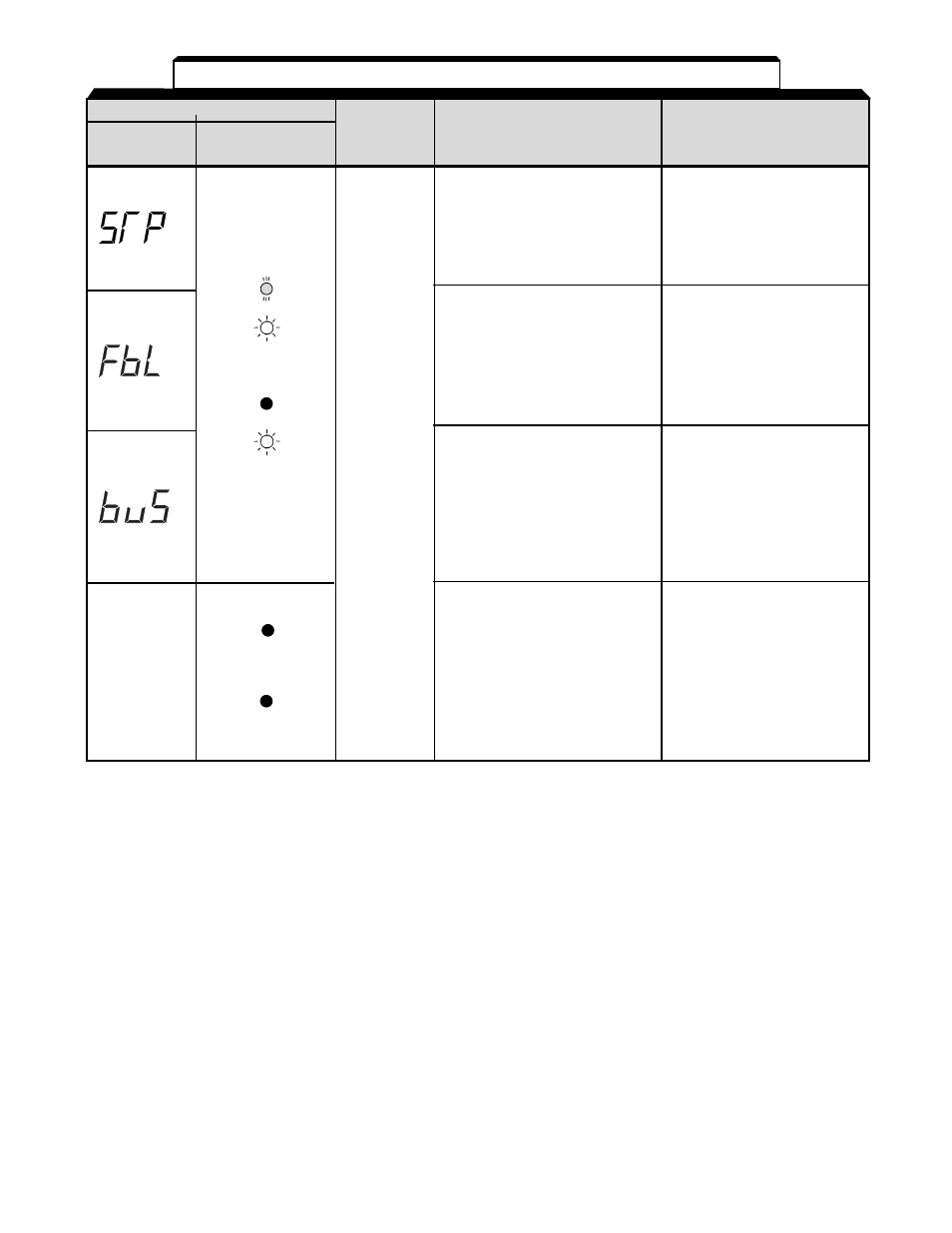
Fault Display
Digital
RUN (Green)
Drive
Explanation
Causes and
Operator
ALARM (Red)
Status
Corrective Actions
STP (Emergency stop)
Check the external circuit
The drive stops
(sequence).
according to parameter
n005 after receiving the
emergency stop fault
signal.
FBL (PID feedback loss
Check the mechanical
detection)
system and correct the
PID feedback value drops
cause, or increase the
below the detection level.
value of n137.
When PID feedback loss is
detected, the Drive operates
according to the n136 setting.
Option card
Check the
communications fault
communication devices
Communication fault has
or communication
occurred in a mode that
signals for noise and
run command and
power supply.
frequency reference are
set from the communication
option card.
• Insufficient power
Check the following:
supply voltage
• Power supply voltage
• Control power supply
• Main circuit power
fault
supply wiring is
• Hardware fault
connected.
• Terminal screws are
securely tightened.
• Control sequence.
Replace the drive.
Table 6-2. Fault Displays and Corrective Actions - Continued
For display/clear of fault history, refer to page 6-8.
or
__
(OFF)
Note 1:
This fault display only available on drive model numbers CIMR-V7AM25P51, 27P51, 45P51, and 47P51
(MVA025, MVA033, MV015, and MVB018). All other drive ratings display “0L” when a ground fault
condition occurs.
Stops
according to
parameter