Appendix 4 - peripheral devices, Appendix 4, Appendix 4. peripheral devices – Yaskawa V7 Drives User Manual
Page 133: Caution warning, A4-1
A4-1
Appendix 4. PERIPHERAL DEVICES
The following peripheral devices may be required to be mounted between the AC main circuit power
supply and the Drive input terminals L1 (R), L2 (S) and L3 (T).
Never connect a general LC/RC noise filter to the drive output circuit.
Never connect a phase-advancing capacitor to the input/output sides or a
surge suppressor to the output side of the drive.
When a magnetic contactor is installed between the drive and the motor,
never turn it on or off during operation.
For more details on peripheral devices, contact your manufacturer.
Recommended Branch Circuit Short Circuit Protection Peripheral Devices
All NEMA type 4X/12 models require branch circuit short circuit protection in
the form of fuses. Use the recommended fuses listed below. Failure to use
the listed fuses may result in damage to the drive and/or personal injury. All
other non-NEMA type 4 Drives can use either fuses or MCCBs for branch
circuit short circuit protection.
All models have UL evaluated motor overload protection built in. Motor
overload protection is also provided in accordance with the NEC and CEC.
Additional branch circuit overload protection is not required.
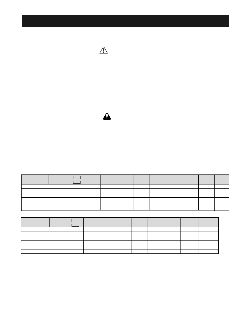
230V 3-Phase
460V 3-Phase
Notes:
(1)
Apply UL designated Class RK5 fuses.
(2)
Apply UL designated Class CC or T non-time delay fuses.
(3)
Model 47P5 rated 21A is only applicable to the NEMA type 4X/12 version.
Input fuse sizes are determined by NEC guidelines, and should not exceed the ratings shown in the table.
Fuse Ratings are based upon 250V fuses for 230V Drives, and 600V for 460V Drives
Fuse Manufacturer’s Designators:
Class CC: KTK, FNQ or equivalent
Class RK5: FRN, FRS or equivalent
Class T: JJS, JJN or equivalent
CAUTION
WARNING
Model
CIMR-V7*
20P1
20P2
20P4
20P7
21P5
22P2
23P7
25P5
27P5
MV
A001
A002
A003
A005
A008
A011
A017
A025
A033
Capacity (kVA)
0.3
0.6
1.1
1.9
3.0
4.2
6.7
9.5
13.0
Rated output current (A)
0.8
1.6
3.0
5.0
8.0
11.0
17.5
25.0
33.0
Rated input current (A)
1.1
1.8
3.9
6.4
11.0
15.1
24.0
33.0
39.6
Max. Time Delay Fuse Rating (A)
(1)
1.8
3.2
6.25
10
17.5
20
25
45
60
Max. Non-Time Delay Fuse Rating (A)
(2)
3
5
10
20
30
45
45
70
80
Max. MCCB Rating (A)
15
15
15
15
20
30
40
50
60
Model
CIMR-V7*
40P2
40P4
40P7
41P5
42P2
43P7
45P5
47P5
(3)
MV
B001
B002
B003
B005
–
B009
B015
B018
Capacity (kVA)
0.9
1.4
2.6
3.7
7.0
11.0
14.0
Rated output current (A)
1.2
1.8
3.4
4.8
9.2
14.8
18/21
Rated input current (A)
1.6
2.4
4.7
7.0
12.0
19.6
23.8 / 27.8
Max. Time Delay Fuse Rating (A)
(1)
2.8
4
8
12
20
35
45
Max. Non-Time Delay Fuse Rating (A)
(2)
5
7
12
20
35
60
70
Max. MCCB Rating (A)
15
15
15
15
20
30
40