KACO blueplanet 6400xi User Manual
Page 10
blueplanet Operating and Installation Instructions 6400xi - 7600xi
Page 11
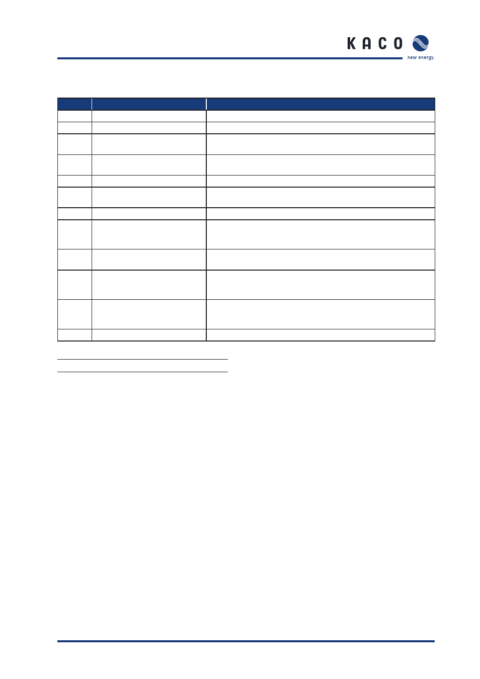
Operating States
Status
Explanation
Comment
0
Inverter has just switched on
Only for a brief period after being fi rst switched on in the morning.
1
Waiting to start
Grid parameters and generator voltage are checked.
2
Waiting to switch off
Insuffi cient generator voltage and generator power. The status before it switches
over to night shutdown mode.
3
Constant voltage regulator
The inverter continues to operate with minimum MPP voltage when the grid-feed
power is low.
4
Grid-feed mode
The inverter is feeding into the grid.
8
Self test
The line relay and the shutdown of the power electronics are tested prior to the
commencement of grid-feed mode.
9
Test mode
For internal operation only.
11
Power limitation
If the generator is producing too much power, the inverter limits to the max. power.
This can occur in the midday hours if the generator has been too largely dimensioned.
This is not a malfunction.
57
Waiting time after a fault
After a fault, the inverter waits a defi ned country-specifi c amount of time before it
switches on (Installation Instructions, section 4, Technical Data).
60
PV voltage is too high for feeding into
the grid
Protective function of the inverter. The inverter can only begin feeding into the
grid once the PV voltage falls below a specifi ed value. The PV voltage is below the
maximum permissible no-load voltage, this status is not an error.
62
Standalone mode
The inverter was switched to standalone mode by the blueplanet Grid-Save. function.
The inverter is disconnected from the public utility grid. The power indicator
percentage refers to the maximum AC power.
64
Output current limit
The AC current is limited once the specifi ed maximum value has been reached.
Table 4.1:
Explanation of the operating states
Fault signals
When these error messages are displayed, the grid-feed is inter-
rupted, the red LED (3) lights up, and the fault signal relay has
switched. This error correction takes a country-specifi c length
of time (see Installation Instructions, section 3, Technical Data).
Afterwards the red fault LED (3) goes out, the fault signal relay
drops out again, and the display signals that it is ready to feed
into the grid once again. Once the fault is gone, the blueplanet
inverter feeds in again.
Many of these fault signals point to a fault in the grid, and are,
therefore, not an operational fault on the part of the bluepla-
net inverter. The minimum triggering levels are determined by
applicable standards (e.g. VDE0126-1-1 or UL 1741), and the
inverter must switch off if the permitted values are exceeded.
S e c t i o n 4 ·
O p e r a t i o n