Caution, Warning, Danger – KACO blueplanet 6400xi User Manual
Page 29: Action
Page 30
blueplanet Operating and Installation Instructions 6400xi - 7600xi
!
CAUTION
The voltage of the solar generator must be
measured before connecting the DC leads to the
inverter terminals. The DC voltage must not exceed
the max. generator voltage because this would
destroy the unit.
ACTION
Before connecting the PV generator to the blueplanet, check
that the PV generator is not grounded.
– Measure the DC voltage between the protective ground
(PG) and the positive lead and between the protective
ground (PG) and the negative lead of the PV generator.
– If stable voltages can be measured, this indicates a
ground fault in the PV generator or its wiring. The ratio
between the measured voltages gives an indication as to
the location of this fault. Rectify this fault before taking
any further measurements.
– Measure the electrical resistance between the protective
ground (PG) and the positive lead and between the
protective ground (PG) and the negative lead of the PV
generator.
– Low resistance (< 2 MΩ) indicates a high-impedance
ground fault of the PV generator, which must be fi xed
prior to continuing with the installation.
Once the wiring in the connection box is installed the pro-
tective cover over the terminals must be secured using the
included screws and must not be opened unless the switch is
in the off position, the AC breaker is in the off position, and
the PV array is powered down with an opaque cover or other
equivalent method to assure there is no DC voltage present in
the box. The connection box should be considered the same
as any other external DC disconnect switch which has live
conductors inside.
Circuit board fuse
The power section has two internal circuit board fuses. These
are labelled F801 or F0901 on the circuit board.
F0901:
Model: 179200 5x20 time-lag 250 V
AC
/ 1.6 A
Manufacturer: SIBA
!
WARNING
For continued protection against risk of fi re, replace
only with same type and ratings of fuse.
S e c t i o n 5 ·
I n s t a l l a t i o n a n d S t a r t - U p
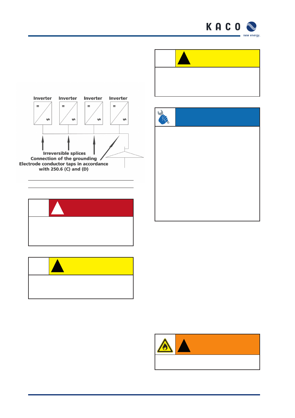
(B) Grounding multiple inverters:
Use a DC GE (Grounding Electrode – ground rod) and run an
appropriately sized conductor from the DC GE to the AC GE.
This will become a GEC for the inverters. Then use a short
appropriately sized conductor jumper to each inverter that is
irreversibly spliced to the GEC.
Figure 5.6: System grounding-multiple inverters
!
DANGER
To ensure maximum protection against hazardous
contact voltages while assembling photovoltaic
installations, both the positive and the negative
leads must be strictly isolated electrically from the
ground potential (GP).
!
CAUTION
Risk of damage.
Be sure that the polarity is correct when you make
the connection. Connecting it wrongly will cause
damage to the inverter.