KACO blueplanet 6400xi User Manual
Page 28
blueplanet Operating and Installation Instructions 6400xi - 7600xi
Page 29
230.82.6: The type of equipment connected to the supply
is listed, with subsection six identifying solar electric
systems as permissible.
All components within a UL 1741 compliant inverter must pass
evaluation spacing, voltages and currents that the inverter is
rated for. The UL 508 standard, industrial control equipment,
auxiliary devices has provisions for testing manually operated
switches. The integrated switch passed the UL 508 standard
under the fi le E304888 for use within a UL 1741 approved grid
tied inverter. The switch was tested 6000 operating cycles at
the nominal AC and DC voltages and currents as noted in table
one below. Additional operating cycles of 4000 resulted in a
total of 10000 successful operating cycles. The switch was de
constructed and evaluated under a pass fail criteria.
As referenced in the NEC, subsection 690.17, the switch must
meet applicable voltage and current ratings. The AC and DC
switch ratings are detailed in this table:
AC / DC Disconnect
Inverter Models
6400xi
7600xi
DC Nominal
Voltage: VDC
600 V
550 V
550 V
DC Nominal
Current: IDC
4 x 16 A
21 A
24 A
The disconnect solution offered by KACO new energy complies
with all applicable NEC, and UL 1741 requirements. The use of
an integrated disconnect with the inverter is potentially safer
due to less electro mechanical connections. The only require-
ment which would necessitate an individual disconnect would
be the specifi c ruling of the utility requiring a UEDS.
Figure 5.4: DC and night switch
The night time start switch is located on the right side of the
connection box. Press and hold the start switch for up to 5 sec-
onds to wake the inverter when there is no DC input voltage.
This allows the user to display the power that was produced
during that day.
5.4 Grounding the inverter
Grounding must be done according to the NEC (National
Electric Code) and any applicable local electric codes! The
inverter has two sides of grounding we need to consider.
System ground (grounding): connecting the circuit to ground
(i.e. neutral of a split single phase).
Equipment ground (bonding): Connecting all non-current
carrying metal parts to ground (array structure, metal enclosure,
module frame)
The AC Grounding Electrode Conductor (GEC) shall be sized
as required by NEC 250.66 and the GEC does not have to be
larger than #6 copper or #4 aluminum if connected to Rod,
Pipe or Plate Electrodes!
The DC Equipment Grounding Conductor (EGC) shall be sized
in accordance with NEC 250.122, if ground fault protection
is used. Otherwise, it should be the same size as the current
carrying conductor!
(A) Grounding single inverters:
For the AC side (system ground) use a continuous irreversibly
appropriately sized conductor bare or insulated conductor
(GEC) to ground the Inverter to the AC GE (Grounding Electrode
- ground rod or in some cases the main water line). If the
ground rod is unavailable, splice irreversibly to the AC GEC.
The DC side (equipment ground) should start at the PV array.
All non-current carrying exposed metal parts of equipment,
raceways, and other enclosures of the PV system shall be
grounded according to NEC 690.43 (e.g. each PV module,
combiner and junction box, metal roofi ng, mounting structure,
DC disconnect, and Inverter). The grounding equipment must
be listed and labeled.
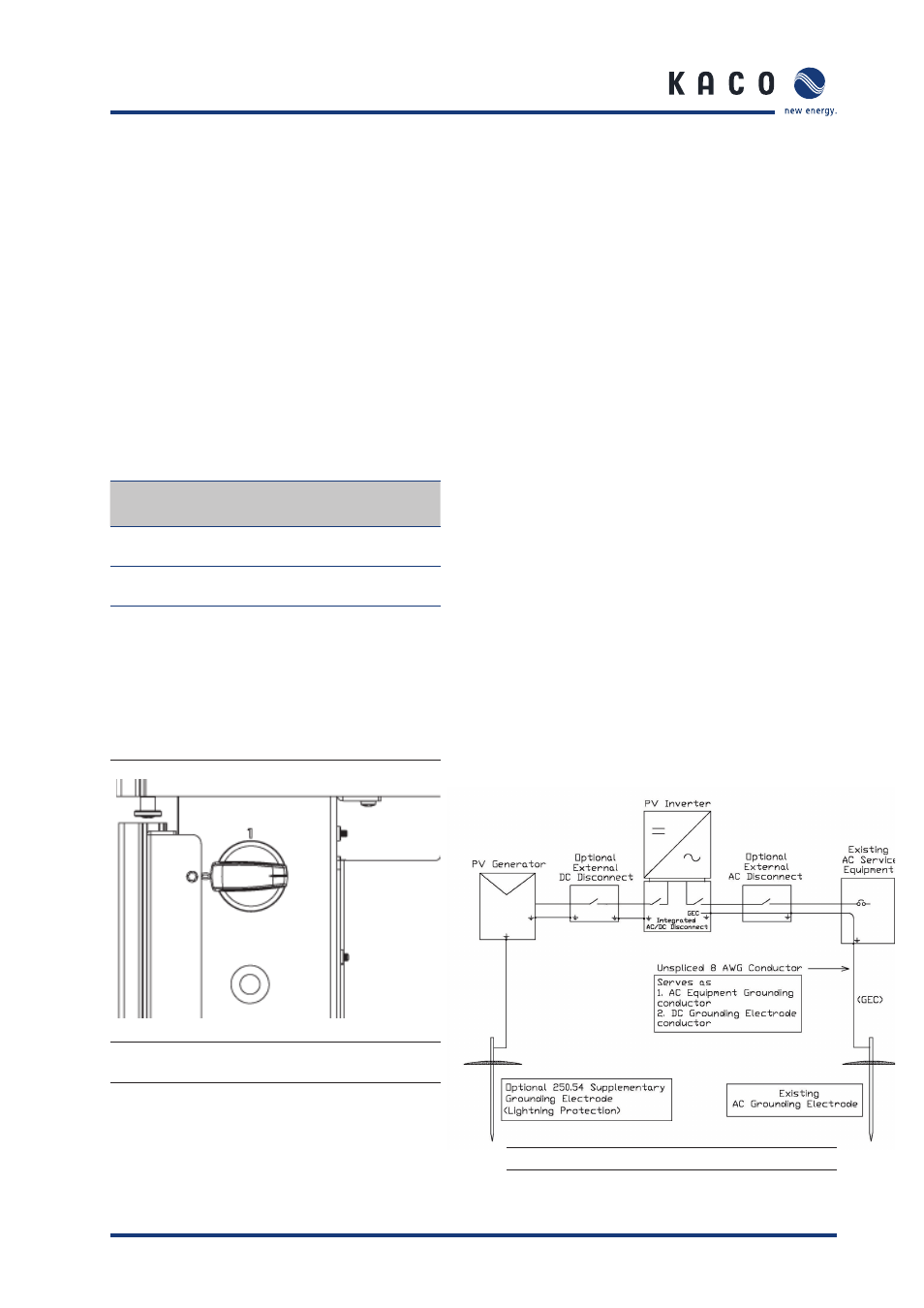
Figure 5.5: System grounding
S e c t i o n 5 ·
I n s t a l l a t i o n a n d S t a r t - u p