Danger, Warning, Caution – KACO blueplanet 6400xi User Manual
Page 32: Action
blueplanet Operating and Installation Instructions 6400xi - 7600xi
Page 33
NOTE
Use Copper Conductors only.
The following AC over-current protection must be used for the
installation of the inverter.
– blueplanet 6400xi →
40 A Breaker
– blueplanet 7600xi
→
50 A Breaker
!
DANGER
Risk of electric shock at live connections.
Check that the power lead is voltage-free before
inserting it into the connection box.
!
WARNING
To reduce the risk of fi re, connect only to a circuit
provided with the required branch-circuit overcur-
rent device sized in accordance with the National
Electrical Code, ANSI/NFPA 70. The maximum size
overcurrent device shall not be more than 50 A for
the 6400xi and the 7600xi.
NOTE
Be sure to use cables with a suffi ciently large cross-section
to avoid excessive line impedance between the building’s
distribution box and the respective blueplanet unit.
When the line impedance is high, i.e. long AC-side leads,
the voltage at the line terminals of the inverter will increase
as power is being fed in to the grid. The inverter measures
this voltage. If the voltage at the grid terminals exceeds the
line overvoltage limit, the inverter will switch off due to line
overvoltage. This condition must be taken into consideration
when wiring the AC and dimensioning the AC lead.
!
CAUTION
Check that the leads are properly connected.
ACTION
Once again, ensure that all connected leads are fi rmly
connected.
PV generator connection
The PV generator leads are connected on the fuse holders
inside of the connection box terminal block.
Fuse for PV+ and PV-:
Model: PV- 10 A10F, 10 A, 1000 V, 10 x 38 mm,
Manufacturer: Bussmann
!
WARNING
For continued protection against risk of fi re, replace
only with same type and ratings of fuse.
!
CAUTION
Do not open the fuse holder under load. Before
opening the fuse holder switch off the DC discon-
nect switch.
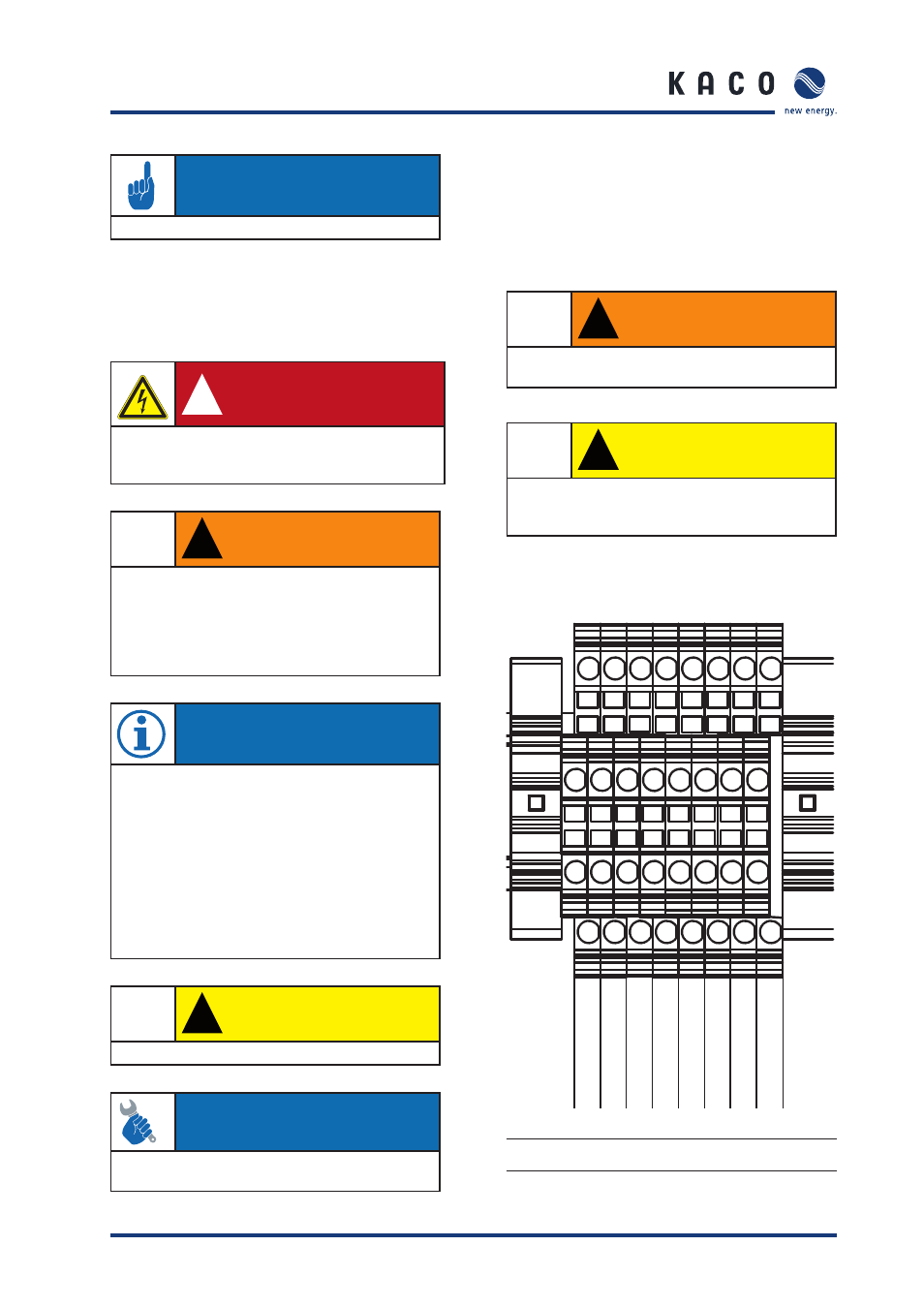
5.7 Interfaces
Figure 5.20: Interface terminals
S e c t i o n 5 ·
I n s t a l l a t i o n a n d S t a r t - U p
GND
GND
-
+ 5 V
, 1
0
0 m
A
R
S4
85 A
R
S4
85 A
R
S4
85 B
R
S4
85 B
S
-
S
+
Er
ro
r
-
Er
ro
r
+
SY
M
+
S
Y
M
+
SY
M
-
SY
M
-
lo
w
er l
ev
el
up
p
er l
ev
el