6 torque requirements, 7 electrical system wiring diagrams – Magnum Energy Mini Magnum Panel (MMP Series) User Manual
Page 24
Page 15
©
2013 Magnum Energy, Inc.
Installation
2.5.3 Wire
Routing
Before connecting any wires, determine all wire routes to and from the MMP enclosure/inverter.
Typical routing scenarios are:
• AC input wiring from the main AC panel or from a generator to the MMP enclosure
• AC input and output from the MMP enclosure to the inverter
• DC wiring from the batteries to the MMP enclosure
• DC wiring from the inverter to the MMP enclosure
• AC output wiring from the MMP enclosure to the AC sub-panel or to dedicated circuits
• Battery Temperature Sensor cable from the inverter to the batteries
• Remote control cable to the inverter through the MMP enclosure
• Ground wiring to and from the MMP enclosure
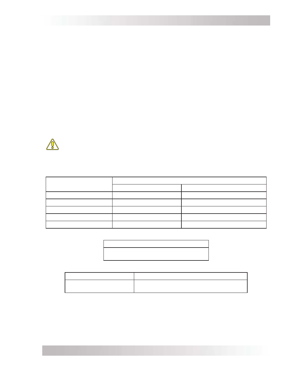
2.6 Torque
Requirements
Follow the specifi c torque recommendations below to ensure your fasteners are tightened suffi ciently.
To ensure your connections are correct, you should use an accurate, quality torque wrench. It is
highly recommended to go back over all fasteners and re-torque after fi ve days and every six months
thereafter.
CAUTION: AC and DC power/wire connections that are under-torqued could become
loose and result in a fi re hazard. On the other hand, over-tightening a bolt could cause
the fastener to be snapped off.
Table 2-1, Torque Values for Busbars
Torque values for the ground busbar, DC negative busbar, and DC positive busbar
(these busbars have different torque values for the small and large screws)
Wire Size
Busbar Screw Size Torque Values
10-32 (Small Screw)
5/16-24 (Large Screw)
#14 to #10 AWG
15 in. lbs. (1.7 N-m)
35 in. lbs. (4.0 N-m)
#8 AWG
20 in. lbs. (2.3 N-m)
40 in. lbs. (4.5 N-m)
#6 AWG
25 in. lbs. (2.8 N-m)
45 in. lbs. (5.1 N-m)
#4 AWG
NA
45 in. lbs. (5.1 N-m)
#3 to #1/0 AWG
NA
50 in. lbs. (5.6 N-m)
Table 2-2, Torque Values for the DC Shunt and DC Disconnect Breaker
3/8-16 Bolt Torque Value
10 to 12 ft. lbs.
(13.6 to 16.3 N-m)
Table 2-3, Torque Values for the AC Terminal Blocks
Wire Size
Slotted M5 Screw Torque Values
#14 to #6 AWG
16.0 in. lbs. maximum
(2.0 N-m maximum)
2.7 Electrical System Wiring Diagrams
Diagrams of the AC and DC wiring for the MMP Series enclosure are shown in Figures 2-5 and
2-6, and are provided to assist you or your system installer. Due to the variety of applications and
differences in local and national electrical codes, these wiring diagrams should be used as general
guidelines only. They are not intended to override or restrict any national or local electrical codes;
and, the diagrams should not be the determining factor as to whether the installation is compliant,
that is the responsibility of the electrician and the on-site inspector.