A6 installing optional dc breakers – Magnum Energy Mini Magnum Panel (MMP Series) User Manual
Page 63
©
2013 Magnum Energy, Inc.
Page 54
Appendix A - Optional Equipment and Accessories
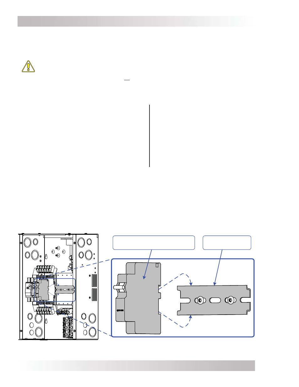
Figure A6-1, Installing DIN Rail-Mounted DC Breakers
DIN
RAIL
-
MOUNTED
DC
BREAKER
(1/2”
WIDTH
)
DIN
RAIL
MOUNTING
TRACK
A6 Installing Optional DC Breakers
The MMP enclosure provides the room to install additional DC circuit breakers that may be used
for charge controllers, a PV-GFP device, and other DC loads. This enclosure has been specifi cally
designed to allow both back-mounted (1” wide)¹ or DIN rail-mounted (1/2” wide)² breakers.
CAUTION: Turning the DC disconnect breaker off only removes the battery power to
the inverter, it does not interrupt power from the battery to the DC load breakers. This
must be accomplished by turning off the DC load breakers themselves. Therefore, to
shut the system off completely, all of the breakers in the MMP enclosure should be
switched to the OFF position.
To install optional DC breakers inside the MMP enclosure:
1. Remove the front cover to the MMP enclosure.
2. For DIN rail-mounted breakers
(refer to Figure A6-1):
For back-mounted type breakers
(refer to Figure A6-2):
a. Install the breaker(s) on the DIN rail mounting
track, and slide all the way to the left side.
b. Place the breaker(s) on the DIN rail track, and
slide a DIN rail clamp tight against the right side
of last circuit breaker; and tighten this clamp to
secure the breaker(s) on the DIN rail track.
c. For each breaker installed, remove only one
knockout (= 1/2” slot) in the front cover.
a. Remove the DIN rail mounting track by
unscrewing the two #8, T15 Torx drive
screws holding this mounting track.
b. Secure the breaker(s) to the panel using
two #8 screws, minimum 1/2” length.
c. For each breaker installed, remove only
two knockouts (= 1” slot) in the front
cover.
3. Ensure the breaker(s) align correctly into the spaces made by the knockouts removed from
the front cover.
4. Wire the breaker(s) to the DC circuit, use Figure A6-3 to assist in wiring the breaker.
5. Replace the MMP front cover and check that the breaker operates correctly.
Note¹ – For the 1/2” wide DIN rail-mounted breakers, use Q-Frame types (QYN Series by CBI).
Note² – For the 1” back-mounted breakers, use E-Frame types (E Series by Carling Technologies,
209 Series by Airpax/Sensata Technologies or CF Series by Heinemann/Eaton).