Magnum Energy Mini Magnum Panel (MMP Series) User Manual
Page 30
Page 21
©
2013 Magnum Energy, Inc.
Installation
2.8.3
Inverter DC Overcurrent Protection and DC Disconnect
In a battery-based inverter system, the NEC/CEC assumes that each ungrounded conductor is
connected to some source that supplies currents in excess of the ampacity rating of the conductor
and could potentially damage that conductor under fault conditions. Because of this, the NEC/
CEC requires that all ungrounded conductors in the inverter’s DC system be protected by an
overcurrent device, this can be either a circuit breaker or fuse. These breakers or fuses are not
intended to protect equipment from damage, but protect the conductor/wire from overheating
which may potentiality cause a fi re. This means the overcurrent device is required to open before
the conductor reaches its maximum current carrying capability, thereby preventing a fi re.
Info: Circuit breakers or fuses that are used on the DC side must be UL listed and DC
rated for the application.
The NEC also requires the inverter system to have a DC disconnect switch to allow the inverter
service providers to isolate the inverter from the battery. The disconnect must be either a DC
rated circuit breaker or switch.
Depending on your model, the MMP enclosure is provided with either a 175-amp or 250-amp
UL listed, high interruption capacity DC rated circuit breaker. These breakers are designed to
interrupt the tremendous amount of current a battery can deliver when short-circuited. They are
also specifi cally designed to have a long enough time delay to prevent the breaker from tripping,
as the inverter requires high current levels when powering heavy loads.
When properly located and used with the minimum DC wire size shown in Table 2-4, these circuit
breakers can provide the inverter system with both the DC overcurrent protection device and a
safety disconnect switch.
2.8.4
Inverter and Battery Bank Wire Sizing
In a low voltage/high amperage system, it is important to use the correct DC wire to achieve
maximum effi ciency from the system and reduce fi re hazards associated with overheating. Always
keep your wire runs as short as practical to help prevent low voltage shutdowns and keep the DC
breaker from nuisance tripping, because of increased current draw.
The size of the DC cables must be correctly sized according to the inverter’s DC current requirements,
DC breaker size, and the minimum voltage drop to the battery bank. If the DC circuit breaker
provided in the MMP enclosure is being used as the inverter’s DC overcurrent protection device,
the cable size must not be less than the minimum DC wire size shown in Table 2-4.
Use Table 2-4 to select the minimum DC wire size based on your MMP model. These recommendations
may not meet the inverter’s continuous current requirements
1
or electrical code requirements.
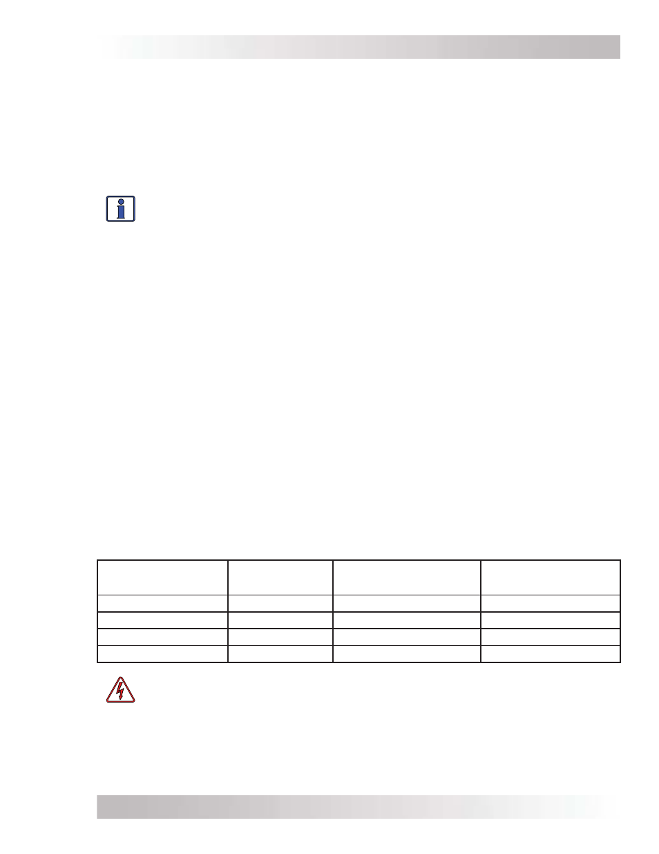
Table 2-4, Recommended DC Wire to MMP Enclosure
MMP Model
DC Circuit
Breaker
Minimum DC Wire
Size (rating)
2
DC Equipment
Grounding Wire Size
3
MMP175-30D
175 amps
#2/0 AWG (195 amps)
#6 AWG
MMP175-60S
175 amps
#2/0 AWG (195 amps)
#6 AWG
MMP250-30D
250 amps
#4/0 AWG (260 amps)
#4 AWG
MMP250-60S
250 amps
#4/0 AWG (260 amps)
#4 AWG
WARNING: If you use a battery or inverter cable smaller than the recommended
minimum DC wire size for your MMP model (as shown in Table 2-4), you must install a
fuse/circuit breaker compatible with this smaller cable to protect against a potential fi re.
Note
1
– Refer to your inverter’s owner’s manual to determine the minimum DC wire requirements.
Note
2
– Wire must be copper with a minimum rating of 300V, 75°C at an ambient temperature of 30°C.
Note
3
– See Section 2.10 for more information on the equipment grounding wire size.