Installation 2.8.5 dc hardware connections – Magnum Energy Mini Magnum Panel (MMP Series) User Manual
Page 31
©
2013 Magnum Energy, Inc.
Page 22
Installation
2.8.5
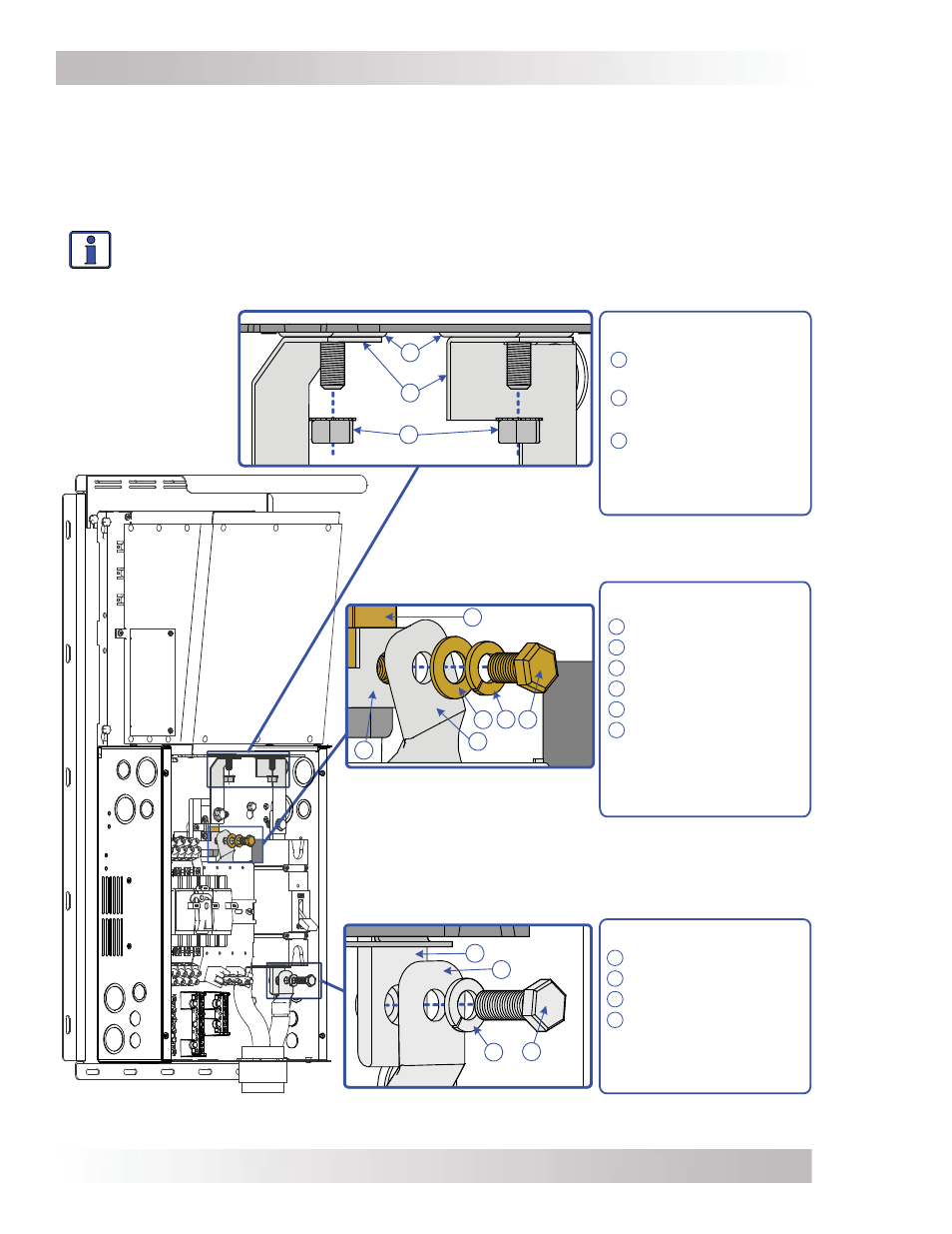
DC Hardware Connections
Do not put anything between the DC cable lug and the DC terminals (i.e., on the DC circuit breaker,
DC shunt, batteries, and inverter/busbars). Ensure the hardware used to hold these connections is
stacked correctly. Incorrectly installed hardware causes a high resistance connection which could
lead to poor inverter performance, and may melt the cable and terminal connections.
Follow Figure 2-9 to connect the DC cables and stack the hardware correctly.
Info:
After making the battery connections
and ensuring they are properly torqued,
cover the outside of the connection with petroleum jelly or an
antioxidant grease/spray.
Do not put jelly/anti-corrosion grease between the terminal and the battery cable.
Figure 2-9, DC Connections – with Magnum Inverter Installed
3
6
1
2
4 5
3
1
2
3
1
2
4
I
NVERTER
DC N
EGATIVE
AND
P
OSITIVE
C
ONNECTIONS
B
ATTERY
N
EGATIVE
C
ONNECTION
B
ATTERY
P
OSITIVE
C
ONNECTION
Bottom of Shunt
Hardware Stack-up:
1 DC shunt
2 DC neg. to ground busbar
3 Neg. (–) battery cable lug
4 Brass fl at washer
5 Brass split-lock washer
6 Brass hex bolt (3/8-16)
DO NOT place anything
between the DC shunt and
the busbar or between the
busbar and the negative
battery cable lug.
Busbar Hardware Stack-
up:
1 Inverter DC terminal
2
DC connection busbars
[(–) to shunt, (+) to DC
disconnect breaker]
3 5/16-18 Nut (Flange/Kep)
DO NOT place anything
between the inverter DC
terminal and the copper
busbar.
Bottom of DC Breaker
Hardware Stack-up:
1 DC breaker terminal
2 Pos. (+) battery cable lug
3 Split-lock washer
4 Hex bolt (3/8-16)
DO NOT place anything
between the DC breaker
terminal and the positive
battery cable lug.