Magnum Energy Mini Magnum Panel (MMP Series) User Manual
Page 28
Page 19
©
2013 Magnum Energy, Inc.
Installation
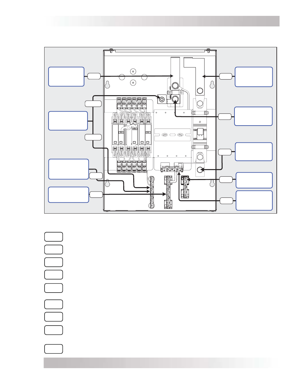
Figure 2-7, DC Wiring Connection Points
DC1
Inverter DC Negative Connection – Top of DC negative busbar connects to Magnum
inverter’s DC negative terminal.
DC2
Inverter DC Positive Connection – Top of DC positive busbar connects to Magnum
inverter’s DC positive terminal.
DC3
Battery Bank Negative Connection – Bottom of DC shunt connects to the battery
bank’s negative terminal.
DC4
Battery Bank Positive Connection – Bottom of the inverter’s DC disconnect breaker
connects to the battery bank’s positive terminal.
DC5
DC Grounding Electrode Connection – The connection point for the MMP/inverter
system to the DC grounding electrode. Use DC5A for greater than #1/0 AWG wires and
DC5B for #6 to #1/0 AWG wires.
DC6
DC Equipment Grounding Connection – The common DC equipment ground point
for all DC equipment used in the MMP/inverter system.
DC7
PV Positive Connection – Connects the positive output of a PV array and the positive
input to the PV charge controller.
DC8
DC Negative Connection – The battery negative common point for connecting
additional DC circuits, such as from the DC negative output of a charge controller or
combining the negatives of DC load circuit breakers.
DC9
Battery Positive Connection – Serves as the battery positive connection point for
additional DC circuits (from charge controller output or connecting to DC load breakers).
Inverter DC
Negative
Connection
DC5A
PV Positive
Connection
DC7
DC9
DC Grounding
Electrode
Connection
DC5B
DC6
DC4
DC3
DC8
Battery Bank
Negative
Connection
Battery Bank
Positive
Connection
Battery
Positive
Connection
DC Negative
Connection
DC Equipment
Grounding
Connection
Inverter DC
Positive
Connection
DC2
DC1
2.8.2
DC Wiring Connection Points
Figure 2-7 shows the connection points for the DC wiring inside the MMP enclosure.