Make all connections on the gauge and fan – Retrotec DucTester 200 Series Residential Applications User Manual
Page 25
Page 25 of 91
©Retrotec Inc. 2015
3. Press
[On]
and then
[Exit]
to view the battery indicator in the top left corner of the screen.
4. If the batteries are less than one quarter full, connect the battery charger for approximately
12 hours.
5. The batteries will charge more quickly if the DM-2 is turned off. A large battery icon will be
displayed on the screen, as shown in Figure 20.
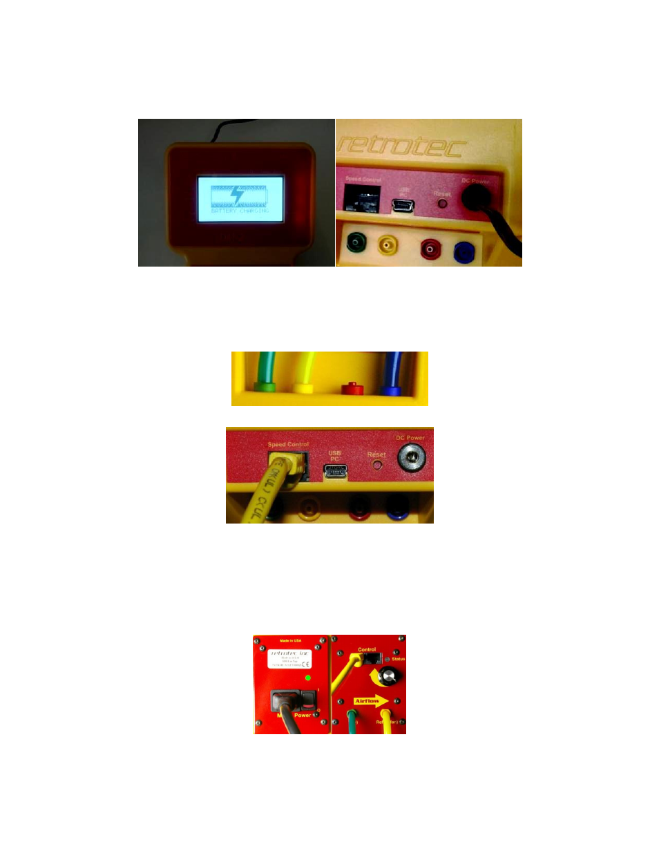
Figure 16: The screen and back view of the DM-2 while the batteries are being charged.
3.6.2. Make all connections on the gauge and fan
6. Often, the yellow, green and blue tubes and the Control Cable are left permanently
connected to the gauge but if not, make those connections.
Figure 17: Pressure ports on the back of the gauge are color-coded to match the tubing.
Figure 18: Electrical connections on the back of the gauge include Control Cable that goes to the DM-2 (shown connected),
USB cable for a PC, reset switch and DC power connection.
7. Connect the power cord to a wall outlet and to the fan. Turn on the power switch. The
Mains Power status light turns green, indicating power is connected. Before connecting the
Control Cable, the manual speed control knob can be used to test run the fan. If the Control
Cable is connected it must be disconnected to use the Manual Speed Control Knob. The
Manual Speed Control Knob must be turned to zero and back on again to re-activate it.
Figure 19: Model 200 Fan Top with power cord, color-coded tubing connections (green and yellow) and Control Cable.