Measure the air handler system flow, For code compliance, Why measure the air handler system flow – Retrotec DucTester 200 Series Residential Applications User Manual
Page 55
Page 55 of 91
©Retrotec Inc. 2015
9. Measure the Air Handler system flow
9.1 For Code compliance
For Code compliance testing, the air handler flow rate is seldom measured because it takes too much
time. Typically air handler flow is calculated by using 400 CFM per Ton or 21.7 CFM per 1000 BTU.
Other Codes require results expressed as CFM of duct leakage per square foot of conditioned floor area.
Small (around 2 Ton) systems with a single return can have their air flow measured at the return.
Measuring from the air handler cabinet is preferred, especially for systems greater than 2 Tons.
9.2 Why measure the Air Handler system flow?
Air handler system flow rates are required to evaluate system performance. Reduced flow rate is one of
the prime reasons that HVAC systems underperform. For air conditioners, insufficient flow leads to
excessively cold coils that will ice up and reduce performance in that way. For heating systems,
insufficient airflow will cause too great a temperature rise that will cause an over-temperature condition
that will cause the furnace to short cycle, reducing its efficiency.
In both cases, insufficient air flow will affect comfort and decrease the system’s ability to maintain the
desired room temperature. This may cause homeowners to mistakenly assume that their system is too
small and replace their unit with a larger one that will make matters even worse.
Variable speed systems are less prone to short cycling due to insufficient airflow unless the load
becomes great enough to cause the unit to operate near its upper limit of capacity at which point it will
short cycle.
9.3 Measure with a DucTester as a powered flow
hood on the return
The Retrotec DucTester and Flow Hood can be used to measure air
flows through supply registers, exhaust fans and other airflow devices,
without affecting their flow rate, by neutralizing the pressure that
would create a resistance to flow. By using the DucTester to create a
Powered Flow Hood, a vent area can be "set to zero", eliminating any
pressure difference. This is unlike using a traditional flow hood, where
the flow hood itself creates a resistance to flow, altering what is being
measured.
Ensure the “n” value on the gauge is set to 0.5. A unique feature of the
Retrotec gauge is that it will allow accurate calculations of air handler
flow rates even if the DucTester is not capable of achieving exactly the
same flow as the air handler is putting out.
On the DM-2 gauge, press the
[Setup]
key and scroll to “N=” and set it
to 0.5.
The Flow Hood looks similar to the Retrotec Pressure Pan, except it
has a ten inch diameter hole in the center and an array of pressure
pickup tubes inside. The hole makes the Flow Hood ready to attach the Flex Duct. Pass the Flange
through the 10 inch hole in the Flow Hood and attach the Flex Duct.
For measuring supply flows, attach the Flex Duct to the inlet (suction) side of the fan over top of the
Range Rings. For measuring return flows; attach the Flex Duct to the outlet (discharge) side of the fan.
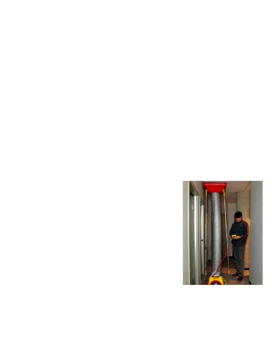
Figure 48: Measuring air flow with a Powered
Flow Hood