Retrotec DucTester 200 Series Residential Applications User Manual
Page 69
Page 69 of 91
©Retrotec Inc. 2015
Appendix A: Calculate Air Flow based on Pressure readings
The air flow being produced by the calibrated fan is a value that can be calculated based on the pressure
developed by the air moving across the inlet side of the fan towards the exhaust. Because the fan is
calibrated, there are known values describing the mathematical relationship between the fan pressure,
which is measured across the fan inlet, and the resulting air flow through the fan.
The Fan Pressure needed to calculate the fan flow is the difference between the pressure at the pickup
and the pressure in the vicinity of the inlet side of the fan. The fan pressure pickup is located inside the
fan near the inlet side of the fan. Self-referencing fans such as the DU200 have the reference port built
in, and it is placed to measure the ambient pressure in the vicinity of the inlet side of the fan. It is
important to set the Device on the gauge to DU200 because that tells the gauge not to adjust the “PrB”
value before calculating flow. Such an adjustment is required in the case of flow toward the operator
when the fan is not self-referenced.
Each fan and range combination has a different flow equation. For each fan and range combination
available, the variables needed to calculate flow are listed in the table below. N and K values depend on
the type of fan and the Range Plate/Ring being used.
Since both the fan pressure pickup and the reference for the fan pressure (yellow and green ports on
the fan connected to the gauge) are on the inlet side of the fan, “PrB”, will always show the correctly
referenced fan pressure and can be used directly as the fan pressure, FP, value in the flow equation.
To determine the fan flow for a particular Fan Pressure, insert the values measured for FP and DP, and
the N and K values from the table into the following equation:
Flow CFM = (FP − DP × K1)
N
× (K + K3 × FP)
Where:
FP
is the fan pressure from Channel B displayed as “PrB”
DP
is the duct pressure from Channel A displayed as “PrA”
There are two conditions for
FP
that must be met before the calculated flow can be considered valid.
The absolute value of
FP
must be greater than the minimum fan pressure,
MF
, from the table and
greater than a factor calculated from the duct pressure,
DP
, and
K2
from the table:
So before calculating flow ensure that: |FP| > MF
And: |FP| ≥ |DP| × K2
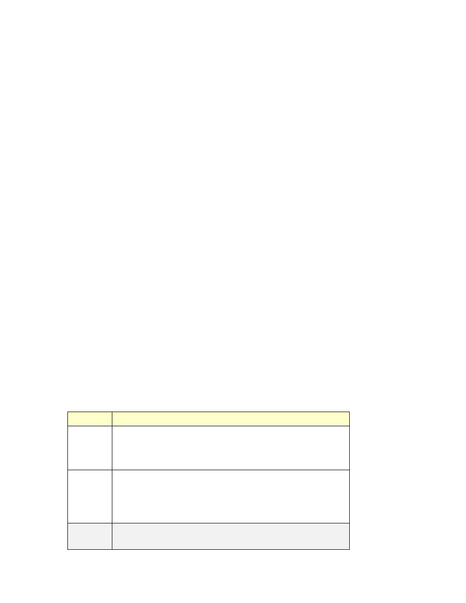
Table 8: N and K coefficients for all supported fans in the gauge.
Range
n
K
K1
K2
K3
MF
Model 200 /
DU220
Open
0.5115 30.7774
0.000 0.2
0.0000
10
Mid
0.5415 5.9146
0.000 0.5
0.0000
25
Low
0.6125 1.0056
-
0.024 0.5
-0.0002
25
Mn
DuctBlaster
Open
0.5032 108.7000
0.000 1.0
0.0000
25
Ring 1
0.5038 40.5000
0.000 1.0
0.0000
25
Ring 2
0.5064 15.2700
0.000 1.0
0.0000
25
Ring 3
0.5140 5.8400
0.000 1.0
0.0000
4
Mn Exhaust
Fan
E1
0.5000 43.7300
0.000 1.0
0.0000
1.0
E3
0.5000 20.7200
0.000 1.0
0.0000
1.0