Retrotec DucTester 200 Series Residential Applications User Manual
Page 81
Page 81 of 91
©Retrotec Inc. 2015
4. Carefully remove old tube. It is easy to damage connector when removing old tube. If removal is
difficult, a small amount of heat from something like a hair dryer may be used to ease removal. If
tubing connector is damaged, replace the connector.
5. Carefully insert tube on connector. Again, a small amount of heat or a bit of silicon lubricant will ease
installation. Make sure that the tube is fully inserted onto the connector, and that the connector is
not damaged or bent.
6. Re-install the Control PCB assembly to the fan shell. Be certain not to over tighten the mounting
screws as it is very easy to over tighten and thus strip out the threads in the plastic fan shell.
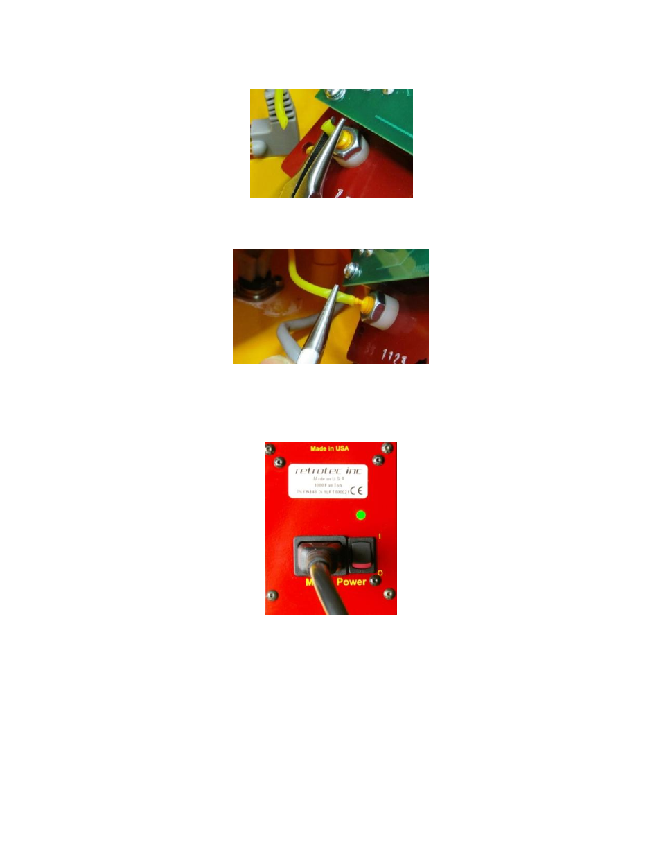
7. Occasionally it may be necessary to replace the Power PCB assembly. The Power PCB assembly has
the power switch on it, and says “Mains Power.” Remove the Power PCB assembly, by removing the
four 8-32 x 5/8” button head screws that secure it to the fan shell, using the 3/32” hex (Allen) key.
8. Gently lift the Power PCB assembly away from the fan shell.
9. Disconnect the Power PCB assembly from wiring harness by carefully pulling all six of the flag
connectors away from the PCB using a pair of pliers. Use a tool to depress the tab on the plug, as
shown, and remove