Mode, Warning – Amprobe Multitest-1000 Continuity-Tester User Manual
Page 27
4.3.1. Mode "
"
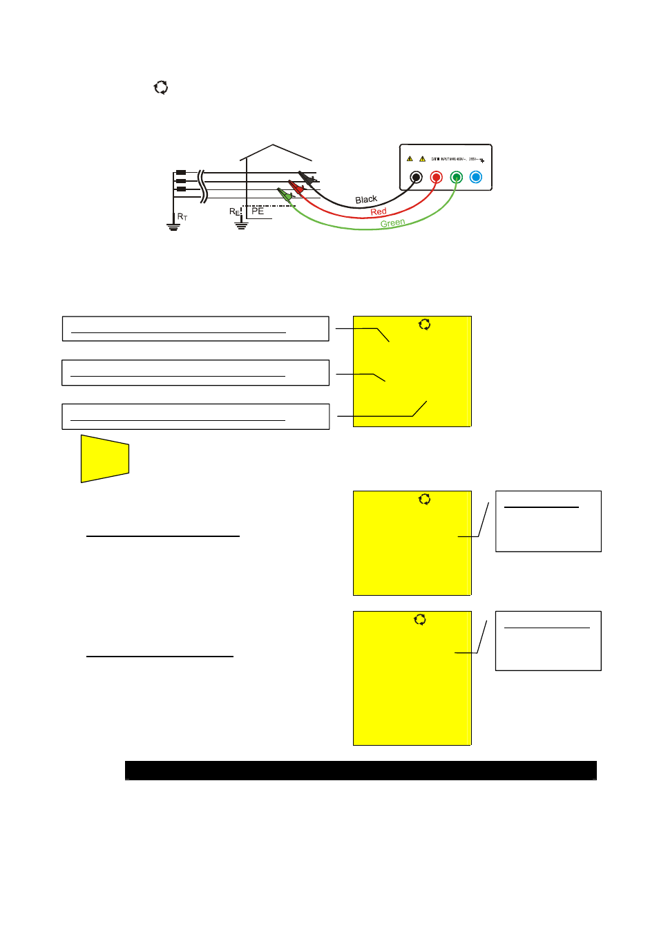
1. Connect the three black, red and green connectors of the untied cables in the corresponding
input terminals of the instrument T1, T2, T3 and the alligator clips to the free ends of the
cables.
B2
B3
B4
B1
L1
L2
L3
N
Instrument connection for phase sequence indication L1=black cable, L2=blue cable, L3=green cable
2. Connect the alligator clips to the three phases of the system under test. The instrument
displays the following screen (before pushing START/STOP key):
386
V
388
V
388
V
Voltage value between Phase1 and Phase2.
Voltage value between Phase3 and Phase1.
Voltage value between Phase2 and Phase3.
4. Press
the
START/STOP key to start the measurement of phase
sequence, one of the following screen will be displayed:
START
STOP
)
123
At the end of the test the instrument
displays the values alongside in case of
correct phase sequence, which means
the black cable is connected to the
phase1=L1, the blue cable to the
phase2=L2 and green cable to the
phase3=L3.
)
ν
213
At the end of the test the instrument
displays the values alongside in case of
wrong phase sequence.
WARNING
Message "213":
indicates that the
phase sequence
is wrong.
Message "123":
indicates that the
phase sequence
is correct.