Measurement procedure for "3p" test mode, Easurement procedure for, Test mode – Amprobe Multitest-1000 Continuity-Tester User Manual
Page 36: 2p 0.93 ω, Warning
4.4.2. Measurement procedure for "3P" test mode
The measurement is taken according to what is prescribed for CEI 64.8, IEC 781, VDE
0413, EN61557-5.
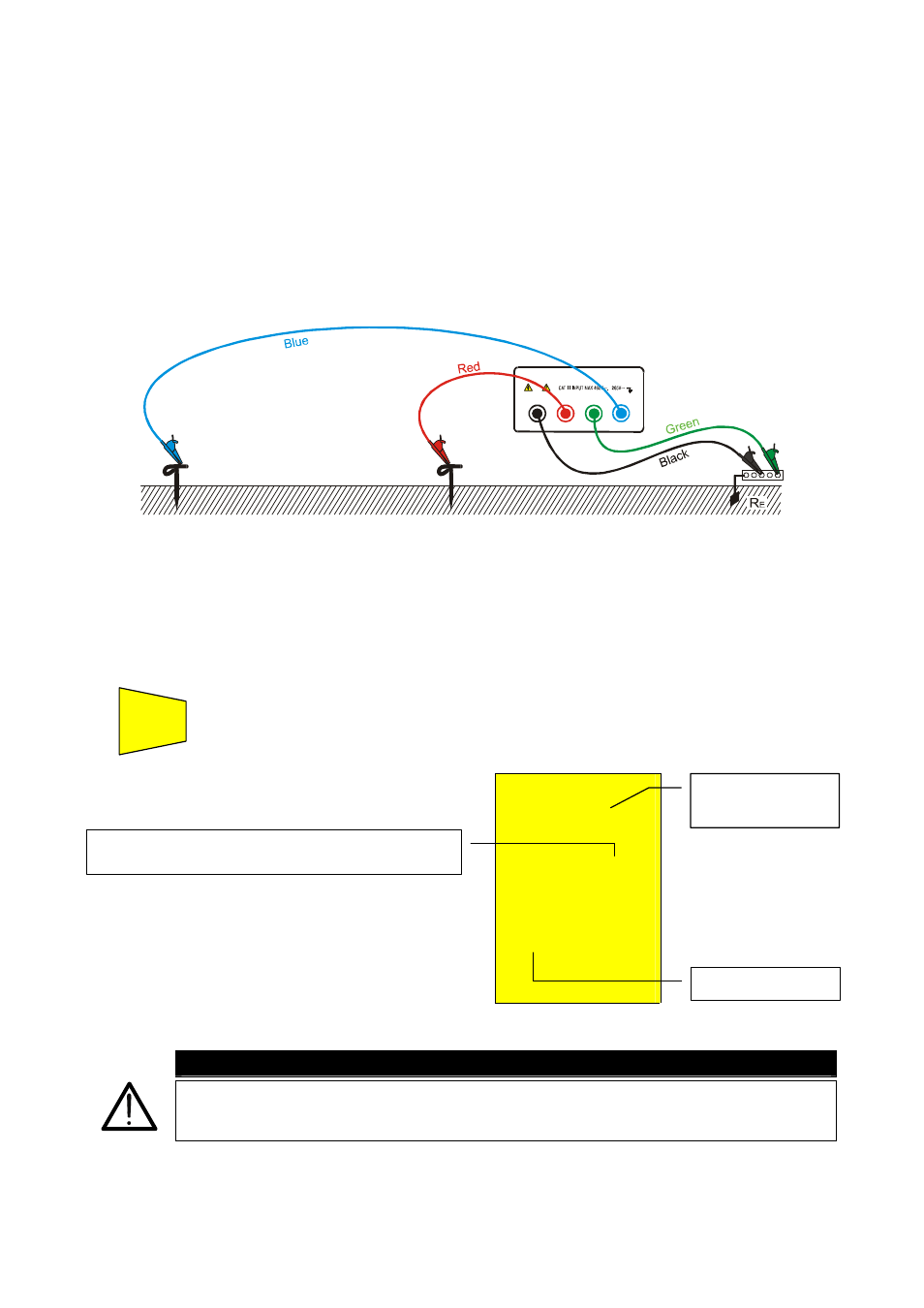
1. Select "3P" earth measurement mode using the F1 key.
2. Connect the Black, Red, Green and Blue cables to the corresponding input terminals of the
instrument T1, T2, T3, T4 (see possible connections in the following picture).
3. Connect the black, and green cables to the earth plant and red and blue cables to the
auxiliary rods.
B2
B3
B4
B1
3 points earth resistance measurement
Measuring small earth plants, current probe must be positioned a distance from the earth
equipment outline corresponding to five times the diagonal of the area of the earth
equipment under test, measuring big earth plants this distance could be reduced up to one
times the diagonal.
4. Press
the
START/STOP key. The instrument starts the test.
)
EARTH
0.96
Ω
2P
0.93 Ω
At the end of the test the instrument
displays the values alongside.
WARNING
The display of “Measuring” means that the instrument is measuring. During
this phase never disconnect test leads.
Average value of earth resistance calculated over
the number of test displayed.
Resistance value
measured
Mode “2P”.
START
STOP