Step 6: connecting the tv and recorder, Cd b, Signal flow – Sony DAR-RD100 User Manual
Page 20
20
GB
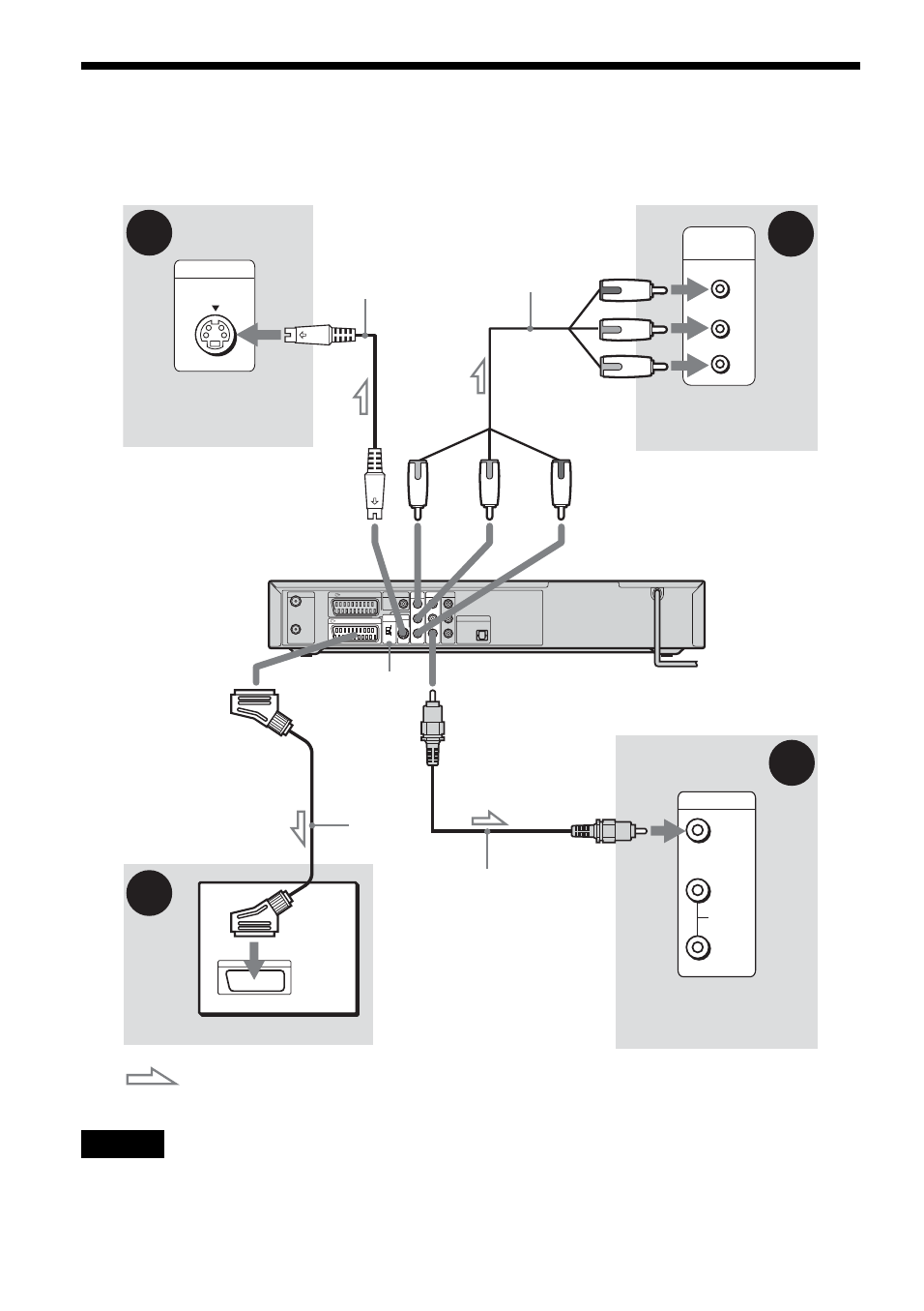
Step 6: Connecting the TV and Recorder
Connect the video cord to view pictures. Select one of following patterns
A
through
D
according to the
input jack on your TV monitor or projector.
Note
Do not connect more than one type of video cord between the recorder and your TV at the same time.
INPUT
S VIDEO
P
R
P
B
Y
COMPONENT
VIDEO IN
VIDEO
AUDIO
INPUT
L
R
AERIAL
IN
OUT
LINE 3 / DECODER
DIGITAL OUT
LINE 1 - TV
COAXIAL
PCM/DTS/
MPEG/
DOLBY DIGITAL
PCM/DTS/MPEG/
DOLBY DIGITAL
COMPONENT
VIDEO OUT
PB/CB
PR/CR
Y
LINE 2 OUT
L
AUDIO
VIDEO
R
LINE 4 IN
L
AUDIO
VIDEO
R
DIGITAL OUT
VIDEO OUT
SELECT
RGB
COMPO-
NENT
OPTICAL
S VIDEO
LINE 2 OUT
C
D
B
A
Video cord
(not supplied)
Component video
cord (not supplied)
TV, projector, or AV
amplifier (receiver)
TV, projector, or AV
amplifier (receiver)
(green)
S-video cord
(not supplied)
TV, projector, or AV
amplifier (receiver)
(red)
(blue)
(green)
(blue)
(red)
: Signal flow
to COMPONENT
VIDEO OUT
to LINE 2 OUT
(S VIDEO)
to LINE 2 OUT (VIDEO)
VIDEO OUT
SELECT switch
DVD recorder
TV
SCART
cord (not
supplied)
to
i
LINE1-TV