2 installing the base module, Installing the base module – Pilz PSSu E F 4DI User Manual
Page 16
Installation
Operating Manual PSSu E F 4DI(T)(R)
21310EN05
16
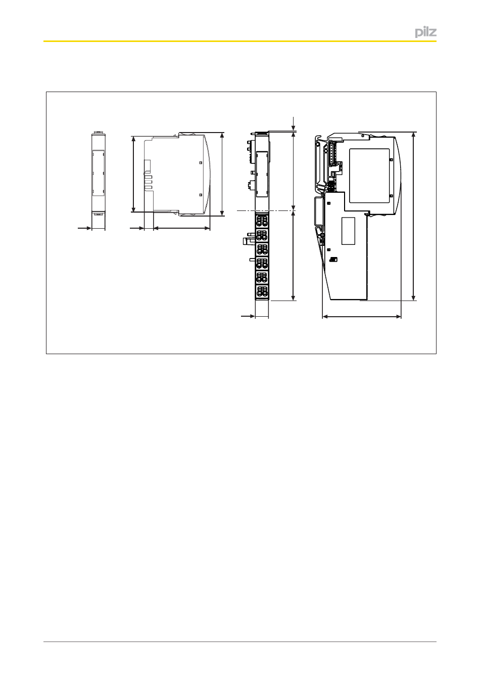
Base modules with six connection levels:
12,6 mm
76 mm
52,1 mm
8,1 mm
67,7 mm
82,0 mm
71,8 mm
0,8 mm
72,6 mm
(2.051")
(0.319")
(2.858")
(0.496")
(2.99")
(3.228")
(2.827")
(0.031")
(2.665")
12,6 mm
(0.496")
154,6 mm
(6.087")
5.2
Installing the base module
Prerequisite:
}
The head module must be installed.
}
If the head module does not have an integrated power supply, a supply voltage module
must be installed to the right of the head module.
Please note:
}
For mechanical reasons it is not possible to mix base modules with screw terminals and
base modules with cage clamp terminals.
}
All contacts should be protected from contamination.
}
The mechanics of the base modules are designed for 50 plug in/out cycles.
Procedure:
}
We recommend that you wire up the base modules before inserting the electronic mod
ules.
}
Slot the groove on the base module on to the mounting rail from below [1].
}
Push the base module back [2] until you hear it lock into position.
}
On the mounting rail, slide the base module to the left until you hear the two lateral
mounting hooks on the adjacent module lock into position [3].