2 display elements, 1 display elements for module diagnostics, 2 display elements for input status – Pilz PSSu E F 4DI User Manual
Page 29: Display elements, Display elements for module diagnostics, Display elements for input status
Advertising
Operation
Operating Manual PSSu E F 4DI(T)(R)
21310EN05
29
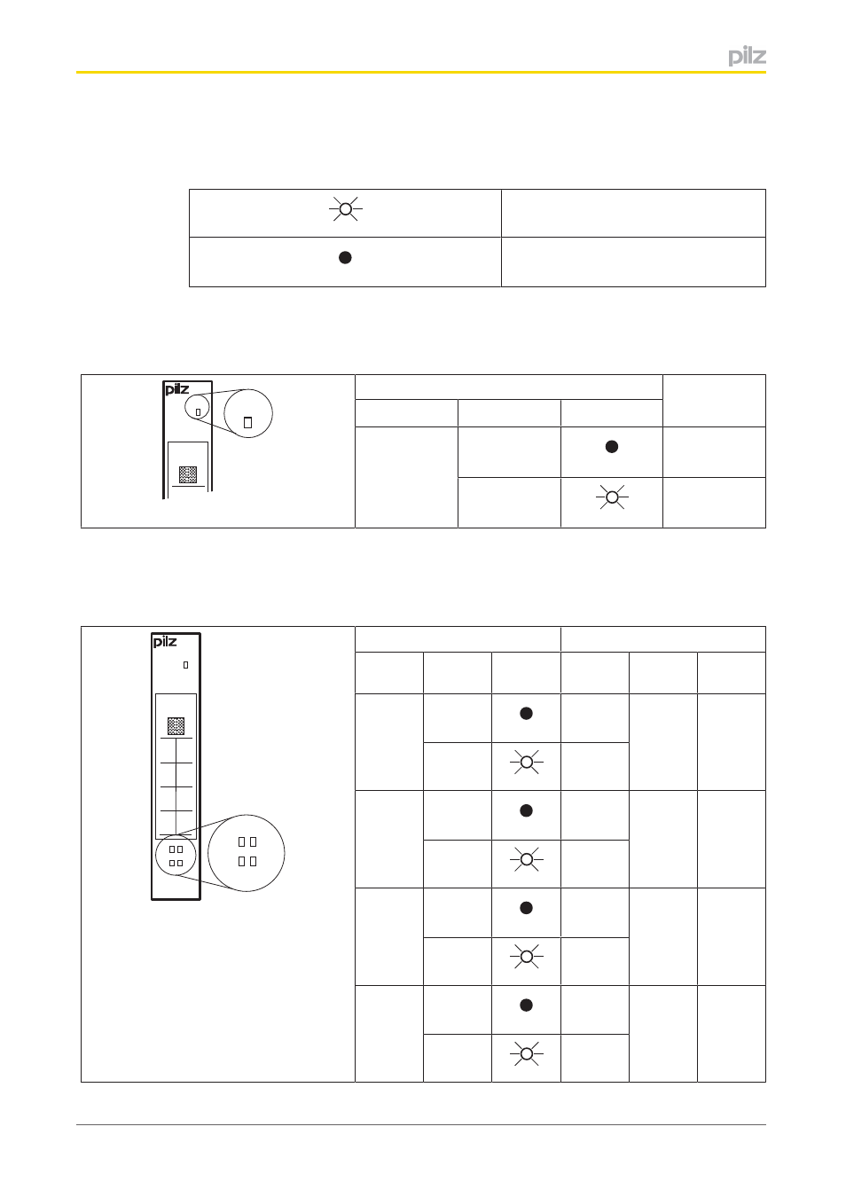
7.2
Display elements
Legend:
LED on
LED off
7.2.1
Display elements for module diagnostics
The module has an LED for displaying module errors ("Err" LED).
Err
11
I0
21
I1
Err
LED
Meaning
Name
Colour
Status
Err
No error
Red
Module error
7.2.2
Display elements for input status
Each input is assigned an LED for displaying the input status (LEDs “11”, “21”, “14” and
“24”).
Err
11 21
12 22
13 23
14 24
11
14
21
24
11
14
21
24
LED
Meaning
Designa
tion
Colour
Status
Signal
Input
Terminal
11
0 signal
I0
(Input 1)
11
Green
1 signal
21
0 signal
I1
(Input 2)
14
Green
1 signal
14
0 signal
I2
(Input 3)
21
Green
1 signal
24
0 signal
I3
(Input 4)
24
Green
1 signal
Advertising
This manual is related to the following products: