6 wiring, 1 general wiring guidelines, 1 mechanical connection of the base modules – Pilz PSSu E F 4DI User Manual
Page 20: Section 6, Wiring, General wiring guidelines, Mechanical connection of the base modules, 6wiring, Din 5264-a
Wiring
Operating Manual PSSu E F 4DI(T)(R)
21310EN05
20
6
Wiring
6.1
General wiring guidelines
Please note:
}
Appropriate wiring must be used to exclude short circuits between the test pulse out
puts and the corresponding input!
}
Appropriate wiring must be used to exclude short circuits between the inputs or to a
supply line!
}
The cable runs for the test pulses may be max. 200 m.
}
Signal lines do not have to be shielded.
}
Use copper wiring.
6.1.1
Mechanical connection of the base modules
Procedure:
}
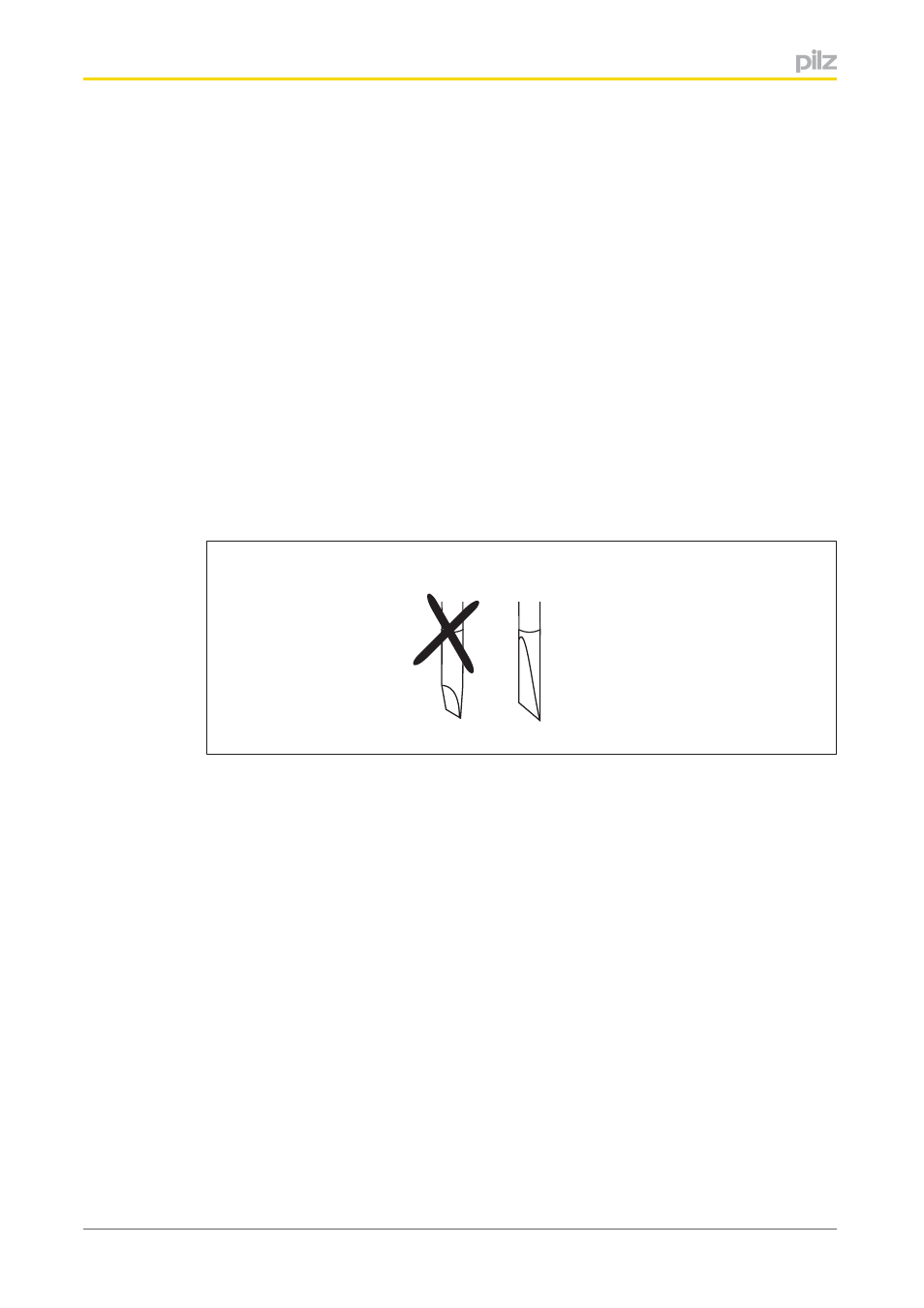
Use a flat blade screwdriver (DIN 5264A)!
DIN 5264-A
}
Strip the wire back 8 mm.
}
If necessary, label the connection level with a colour marker [3].
}
Base module with screw terminals:
–
Use a screwdriver to loosen the screw on the screw terminal [1]
–
Insert the stripped cable into the round fixing hole [2], as far as it will go.
–
Tighten up the screw on the screw terminal.
–
Check that the cable is firmly seated.
}
Base module with cage clamp terminals:
–
Insert the screwdriver [4] into the square hole [1].
–
Insert the stripped cable into the round fixing hole [2], as far as it will go [5].
–
Pull out the screwdriver [6].
–
Check that the cable is firmly seated.