2 terminal configuration, Terminal configuration – Pilz PSSu E F 4DI User Manual
Page 23
Advertising
Wiring
Operating Manual PSSu E F 4DI(T)(R)
21310EN05
23
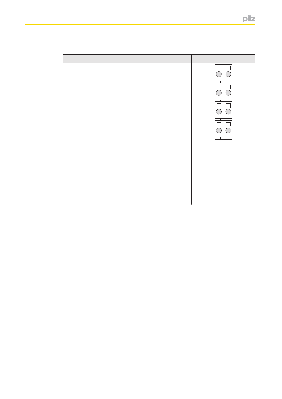
6.2
Terminal configuration
Base module
Terminal configuration
Screw terminals:
PSSu BP 1/8S
PSSu BP 1/8ST
Cage clamp terminals:
PSSu BP 1/8C
PSSu BP 1/8CT
Without Crail:
11: Input I0
21: Input I1
1222: Test pulse output T0
or +24 V output (periphery
supply,
1222 linked within the base
module)
1323: Test pulse output T1
or +24 V output (periphery
supply,
1323 linked within the base
module)
14: Input I2
24: Input I3
21
11
22
12
23
13
24
14
Advertising
This manual is related to the following products: