6wiring, 1 general wiring guidelines – Pilz PSSu E S 2DO 2-T User Manual
Page 26
6.1
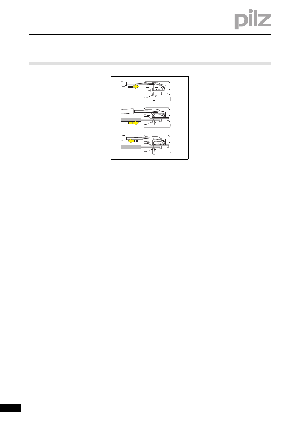
General wiring guidelines
6
Wiring
Pilz GmbH & Co. KG, Felix-Wankel-Straße 2, 73760 Ostfildern, Germany
Telephone: +49 711 3409-0, Telefax: +49 711 3409-133, E-Mail: [email protected]
6-2
][Modulverdrahtung el Sys A + B
Please note:
The minimum cable cross section for field connection terminals on the
base modules is 0.14 mm
2
(AWG26)
The maximum cable cross section for field connection terminals is:
– Digital inputs: 1.5 mm
2
(AWG16)
– Digital outputs: 2.0 mm
2
(AWG14)
– Inputs/outputs on the counter modules: 1.5 mm
2
(AWG16)
– Analogue inputs/outputs: 1.5 mm
2
(AWG16)
– Communication cables: 1.5 mm
2
(AWG16)
– Test pulse outputs: 1.5 mm
2
(AWG16)
– Power supply: 2.5 mm
2
(AWG12)
– Functional earth: 2.5 mm
2
(AWG12)
On base modules with screw terminals:
– If you use a multi-strand cable to connect the I/Os, it is recom-
mended that you use ferrules conforming to Parts 1 and 2 of DIN
46228, 0.14 ... 1.5 mm
2
, Form A or C, although this is not essential.
To crimp the ferrules you can use crimp pliers (crimp form A or C)
conforming to EN 60947-1, such as the PZ 1.5 or PZ 6.5 from
Weidmüller, for example.
– Maximum torque setting: 0.8 Nm
Use copper wiring.
[4]
[5]
[6]