D1 d2 – Altera Avalon Verification IP Suite User Manual
Page 27
1–4
Chapter 1: Avalon-MM Master BFM
Functional Description
Avalon Verification IP Suite User Guide
May 2011
Altera Corporation
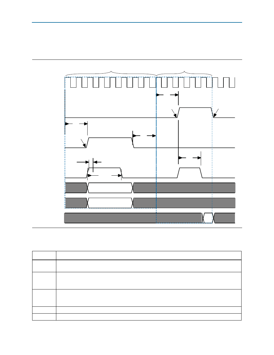
The timing diagram in
shows the sequence of events for an Avalon-MM
Master BFM driving a write followed by a read when the
readdatavalid
signal is not
present.
lists the annotations used in
.
Figure 1–3. Avalon-MM Master Driving Write and Read Transactions with No readdatavalid Signal
CLK
read
write
waitrequest
byteenable[3:0]
writedata[31:0]
readdata
D1
D2
T
init
T
init
S
ci_1
T
wt_1
T
wt_2
S
ci_2
S
rc_1,
S
atc
T
wr
transaction5
transaction6
T
idle
Table 1–2. Key to Annotations in
Symbol
Description
T
init
The initial command latency, which is two cycles for transactions 1 and 2. This time is set by the API
command
set_command_init_latency
.
T
wt_1
The response wait time, which is three cycles. This time is determined by the number of cycles that the
waitrequest
signal is asserted by the slave.The program gets this value using the
get_response_wait_time
command.
T
wt_2
The response wait time for the first read, which is two cycles. This time is determined by the number of
cycles that the
waitrequest
signal is asserted by the slave.The program gets this value using the
get_response_wait_time
command.
T
wr
waitrequest
is always sampled #1 after the falling edge of
clk
.
T
idle
The idle time after a transaction. This time is set by the command
set_command_idle.