D1 d2 – Altera Avalon Verification IP Suite User Manual
Page 48
Chapter 3: Avalon-MM Slave BFM
3–5
Functional Description
May 2011
Altera Corporation
Avalon Verification IP Suite User Guide
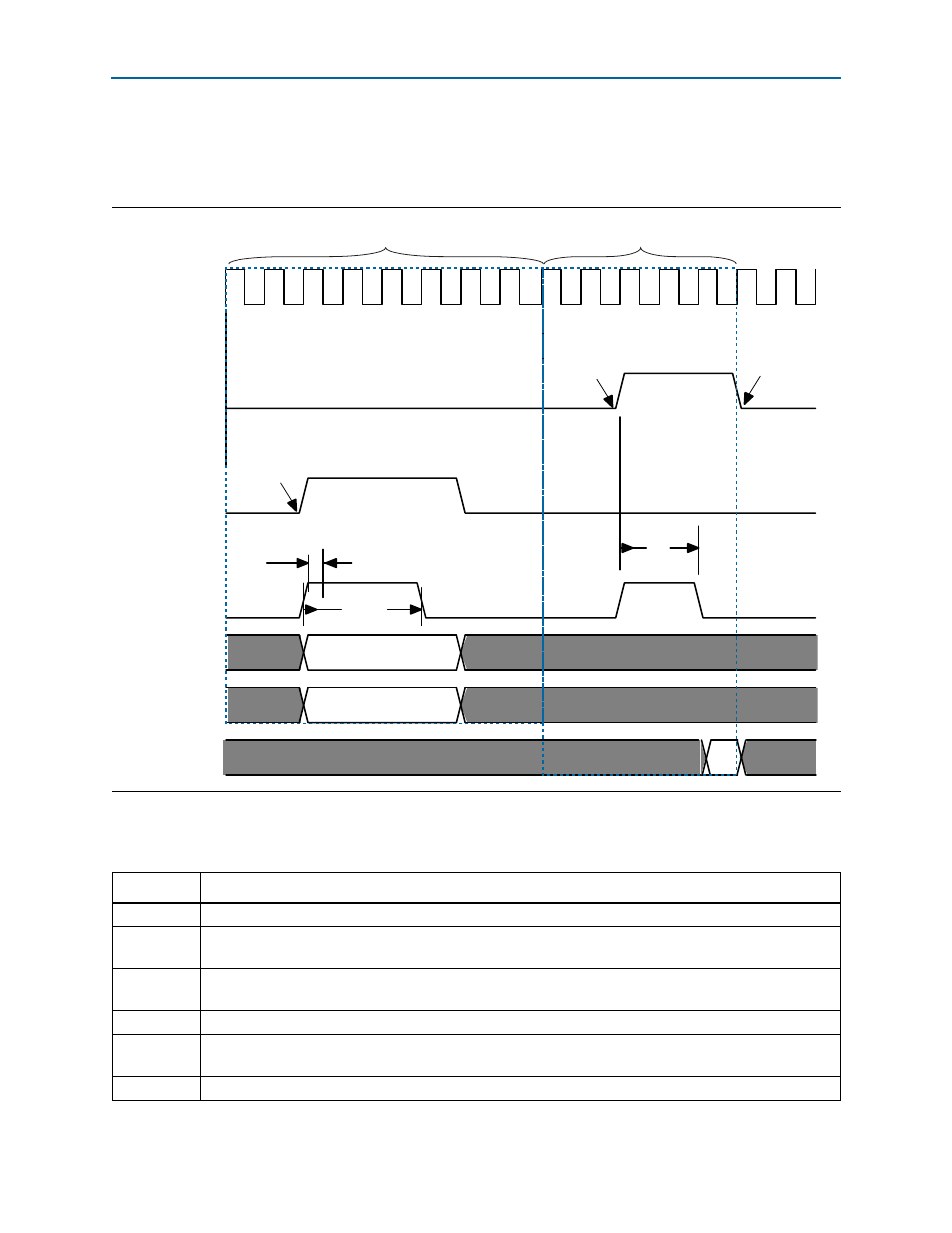
The timing diagram in
illustrates the sequence of events for an Avalon-MM
Slave BFM receiving a write followed by a read when the
readdatavalid
signal is not
present.
lists the annotations used in
.
Figure 3–3. Avalon-MM Slave Receiving Write and Read Commands with No readdatavalid Signal
CLK
read
write
waitrequest
byteenable[3:0]
writedata[31:0]
readdata
D1
D2
S
cr_1
T
wt_1
T
wt_2
S
cr_2
T
wr
transaction5
transaction6
S
rc_1,
S
atc
Table 3–2. Key to Annotations in
Symbol
Description
T
i
The initial command latency which is two cycles for transactions 1 and 2.
T
wt_1
The response wait time which is three cycles. The master gets this value using the
get_response_wait_time
command.
T
wt_2
The response wait time for the first read, which is two cycles. The slave sets this value using the
set_interface_wait_time
command.
T
wr
waitrequest
is sampled #1 after the falling edge of
clk
.
T
rl_1
The response latency for the first read, which is zero cycles. The master gets this time using the
get_response_latency
command.
S
cr_1,
S
cr_2
Signals write and read commands. The event name is
signal_command_issued
.