Connecting input signals, 6 position connector, Inside drive – Applied Motion ST10-Plus User Manual
Page 10: Connector pin diagram
10
ST5/10-S Hardware manual
920-0027 Rev. D
2/7/14
Connecting Input Signals
The ST drives have three types of inputs:
• High speed digital inputs -STEP & DIR- for step & direction commands, encoder following, run/stop & direction,
or general purpose, 5 volt logic.
• Quadrature signals from encoders can also be used.
• Digital input for other signals, 5 -12 volt logic, including an enable (EN) . Digital signal for enabling the drive.
• Analog input for analog speed adjustment - analog velocity 0-5V
All drives include three digital inputs and one analog input. See page 35 for a list of all functions.
• STEP & DIR: digital signals for commanding position. Quadrature signals from encoders can also be used.
• EN - enable . Digital signal for enabling the drive, speed change, or general purpose..
• Analog In: analog velocity 0-5V.
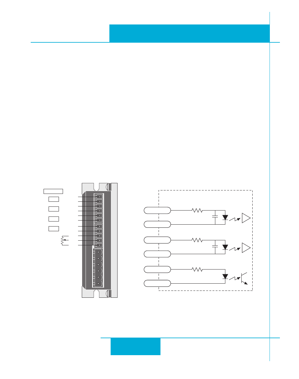
Connector Pin Diagram
GND
AIN
+5V
OUT-
OUT+
EN-
EN+
DIR-
DIR+
STEP-
STEP+
HUB & SCL
IN 1
IN 2
IN 3
OUT 1
680
inside drive
EN-
EN+
DIR-
DIR+
330
330
220
pF
STEP-
STEP+
6 Position Connector
220
pF