Connecting limit switches, Wiring a mechanical limit switch, Cw limit ccw limit – Applied Motion ST10-Plus User Manual
Page 15: St5-s or st10-s drive
15
ST5/10-S Hardware manual
920-0027 Rev. D
2/7/14
Connecting Limit Switches
For point to point SCL and HUB applications, the STEP input can be used as a clockwise end of travel limit and
the DIR input can be used as the counterclockwise end of travel limit. If using SCL, you activate the limits using
the SCL “DL” command, as described in the Host Command Reference manual.
These inputs are differential, which allows you to use signals that are sinking (NPN), sourcing (PNP) or differential
(line driver). The limit inputs are optically isolated.
Input signals must not exceed 5 volts DC unless external current limiting resistors are used in series with STEP+
and DIR+.
For 12 volt logic, add 820 ohm, 1/4 watt resistors
For 24 volt logic, use 2200 ohm, 1/4 watt resistors
Because these inputs can accept high frequency signals, care must be taken in locating the signal wires and drop-
ping resistors. Shielded cables are recommended. Separate any limit sensor wires from the motor wires by at
least 4 inches. If false triggering of a limit occurs, increase the value of the internal digital filter using the EI150
command. This will limit the bandwidth of the STEP and DIR inputs to 100 kHz.
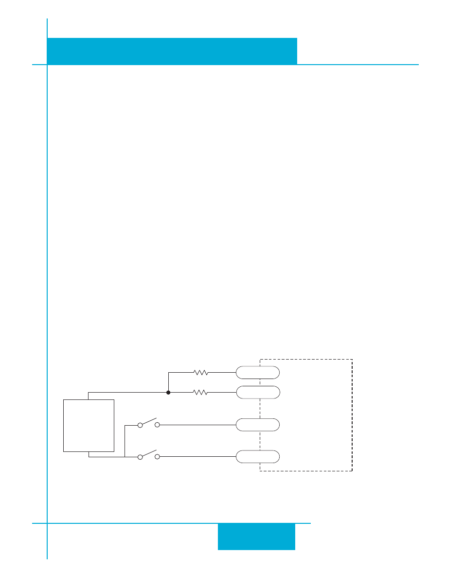
Wiring a Mechanical Limit Switch
You can use normally open or normally closed limit switches. Either way, wire them as shown here.
ST5-S
or
ST10-S
drive
+
5-24
VDC
SUPPLY
-
STEP-
DIR-
STEP+
DIR+
cw limit
ccw limit
R
R
for 24V logic R=2200 ohms
for 12V logic, R=820 ohms
for 5V logic , R not required