Wiring a limit sensor – Applied Motion ST10-Plus User Manual
Page 16
16
ST5/10-S Hardware manual
920-0027 Rev. D
2/7/14
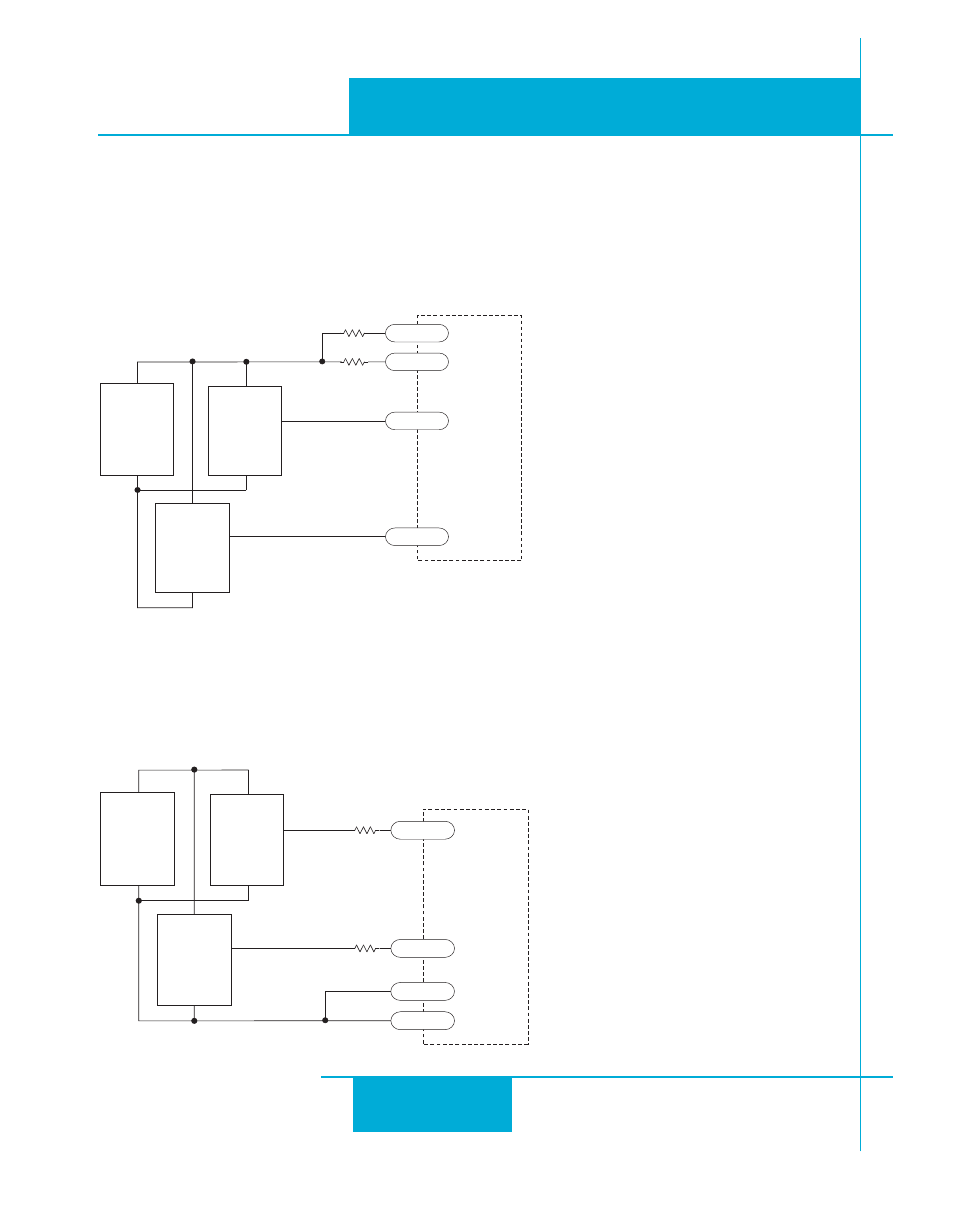
Wiring a Limit Sensor
Some systems use active limit sensors that produce a voltage output rather than a switch or relay closure. These
devices must be wired differently than switches.
If your sensor has an open collector output or a sinking output, wire it like this:
If the sensor output goes low at the limit, select the option ”closed” (DL1). If the output is open, or high voltage,
choose ”open” (DL2).
Other sensors have sourcing outputs. That means that current can flow out of the sensor output, but not into it. In
that case, wire the sensor this way:
+
5-24
VDC
Power
Supply
–
NPN
Limit
Sensor
output
+
–
ST5-S
or
ST10-S
drive
STEP-
DIR-
STEP+
DIR+
cw limit
NPN
Limit
Sensor
output
+
–
ccw limit
R
R
for 24V logic R=2200 ohms
for 12V logic, R=820 ohms
for 5V logic , R not required
+
5-24
VDC
Power
Supply
–
PNP
Limit
Sensor
output
+
–
ST5-S
or
ST10-S
drive
STEP+
DIR+
STEP-
DIR-
cw limit
PNP
Limit
Sensor
output
+
–
ccw limit
R
R
for 24V logic R=2200 ohms
for 12V logic, R=820 ohms
for 5V logic , R not required