Connecting to charger – Computronic Controls Sentinel 150P User Manual
Page 8
SNTL150P-PCSUITE installation & operation
ci0052 p8/28 issue 2 2014-01-09
Connecting To Charger
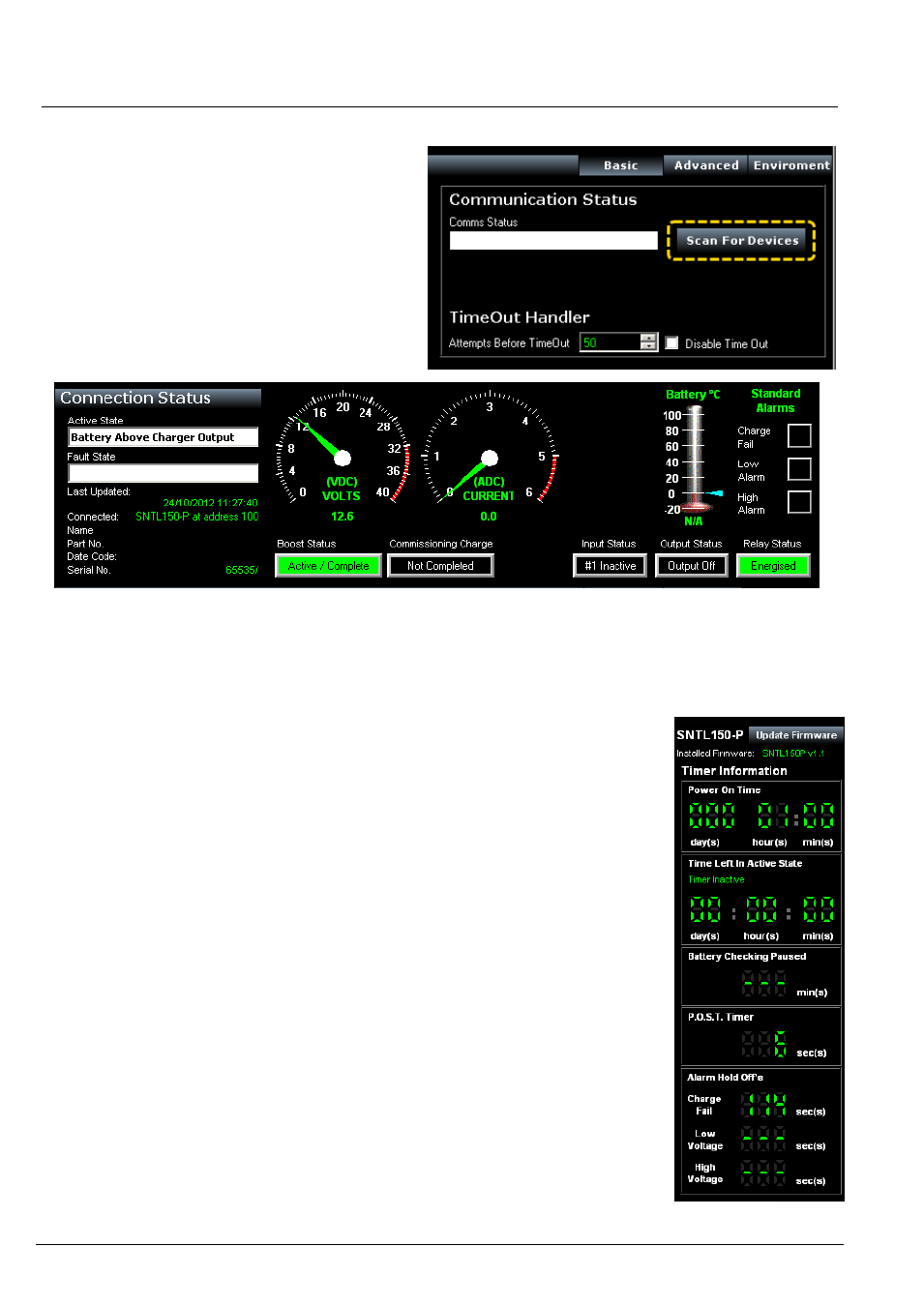
Once connected to charger and SNTL150P has
either DC or AC power, select Scan For Devices to
initiate scan.
Upon successful detection of the SNTL150P the
software suite will automatically connect and start
communicating
See resolving communication errors section (-
page 25) of this document should you have problems
connecting to the SNTL150P
Once communication is established with the unit, the Top & Side Status windows and
indications will become active and reflect the SNTL
150P’s current condition
Top Status Window
In addition to information about voltage, output current and SNTL150P model
information, the Top Status Window provides information regarding its charging state.
Battery (°C) Thermometer - will indicate SNTL150P detected battery temperature
should a remote temperature compensation lead be connected. (Temperature is
shown in °C)
Boost Status
– Will indicate if SNTL150P needs to enter its boost cycle. Indicates if
Waiting to Start, Active or Completed. Once SNTL150P terminal voltage has
increased above boost initiate voltage, then this will become green.
Commissioning Charge
– When SNTL150P is first powered up, it will automatically
enter a prolonged boost extension period, factory set to 6 hours, once complete this
will become green and be marked as complete.
Input Status (if option fitted)
– Shows indication of SNTL150Ps digital input
Output Status
– Shows indication of SNTL150P self-resetting output protection
circuit
Relay Status (if option fitted)
– Shows Fault Relay Status
Side Status Window
The firmware revision installed in the SNTL150P is displayed along with option to
update, Consult updating firmware section within this document.
The side status window will indicate information about timers on the SNTL150P.
Power On Time
– Duration that the SNTL150P has been powered (AC or DC)
Time Left in Active State - How long the SNTL150P has remaining in its current
state.
Time Until Battery Check - How long before next Battery Check is performed.
P.O.S.T. Timer / Boost Initiate Timer -
Time (counting down from 30s) until boost is initiated if battery measured voltage is
below the boost initiate set point or the 6 second POST timer performed on initial
power up or after a Connection Fault
Alarm Hold Off’s – Low, High and Charge Fail alarms are held off for 2 minutes,
should the fault still be present at the end of the hold timer then an alarm will be
indicated.