Introduction – Artesyn MVME8100/MVME8110 Installation and Use (September 2014) User Manual
Page 19
Introduction
MVME8100 / MVME8110 Installation and Use (6806800P25G)
19
VXS Interface
VXS (VITA 41) Specification compliant
Support backplane P0 connector
Form Factor
Standard 6U, one slot
Support 0.8, and 0.85 inch slot chassis
Support heat frame on both sides for Conduction cooled board
Miscellaneous
One front panel RESET Switch
LED front panel status indicators: four user/fail/ready LEDs
Planar status indicators
Boundary scan support
Software Support
VxWorks OS support
Linux OS support
RTM
Compatible with RTM (assembly # 0106852M***)
I/O
One micro DB9 connector for console port on front panel
One USB2.0 type A connector on front panel
One front panel RJ45 connector with integrated LEDs for
10/100/1000 Ethernet channel
PMC/XMC site 1 front I/O and rear PMC I/O
PMC/XMC site two front I/O
Four Serial ports to P2/RTM, two with micro DB9 connectors on RTM
panel and two on planar headers
Two 10/100/1000BASE-T Ethernet channels to RJ45 connectors on
RTM panel
Two 1000 BASE-BX Ethernet SERDES channels to backplane
Two USB2.0 ports to RTM with USB type A connectors on RTM panel
One SATA port to RTM with eSATA connector on RTM
Four GPIOs to planar headers on RTM
Note: The front panel I/O connectors are available only in ENP1 (air
cooled variants). I/O signals in ENP4 (conduction cooled) variant are
accessed through P2 only.
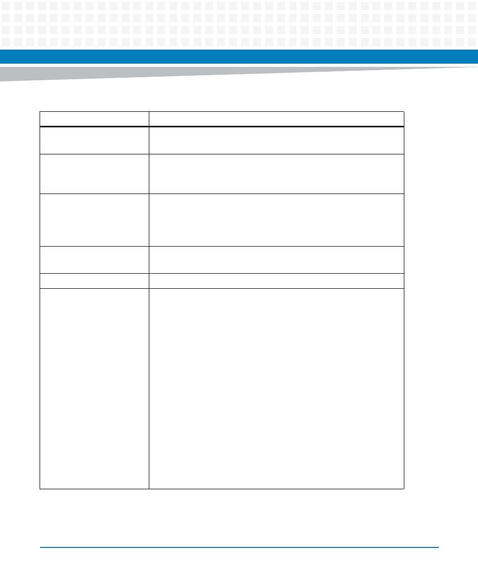
Table 1-1 Features List of MVME8100 (continued)
Function
Features