2 front panel, Figure 3-1, Enp1 board front panel leds, connectors, switch – Artesyn MVME8100/MVME8110 Installation and Use (September 2014) User Manual
Page 52: Controls, leds, and connectors
Advertising
Controls, LEDs, and Connectors
MVME8100 / MVME8110 Installation and Use (6806800P25G)
52
3.2
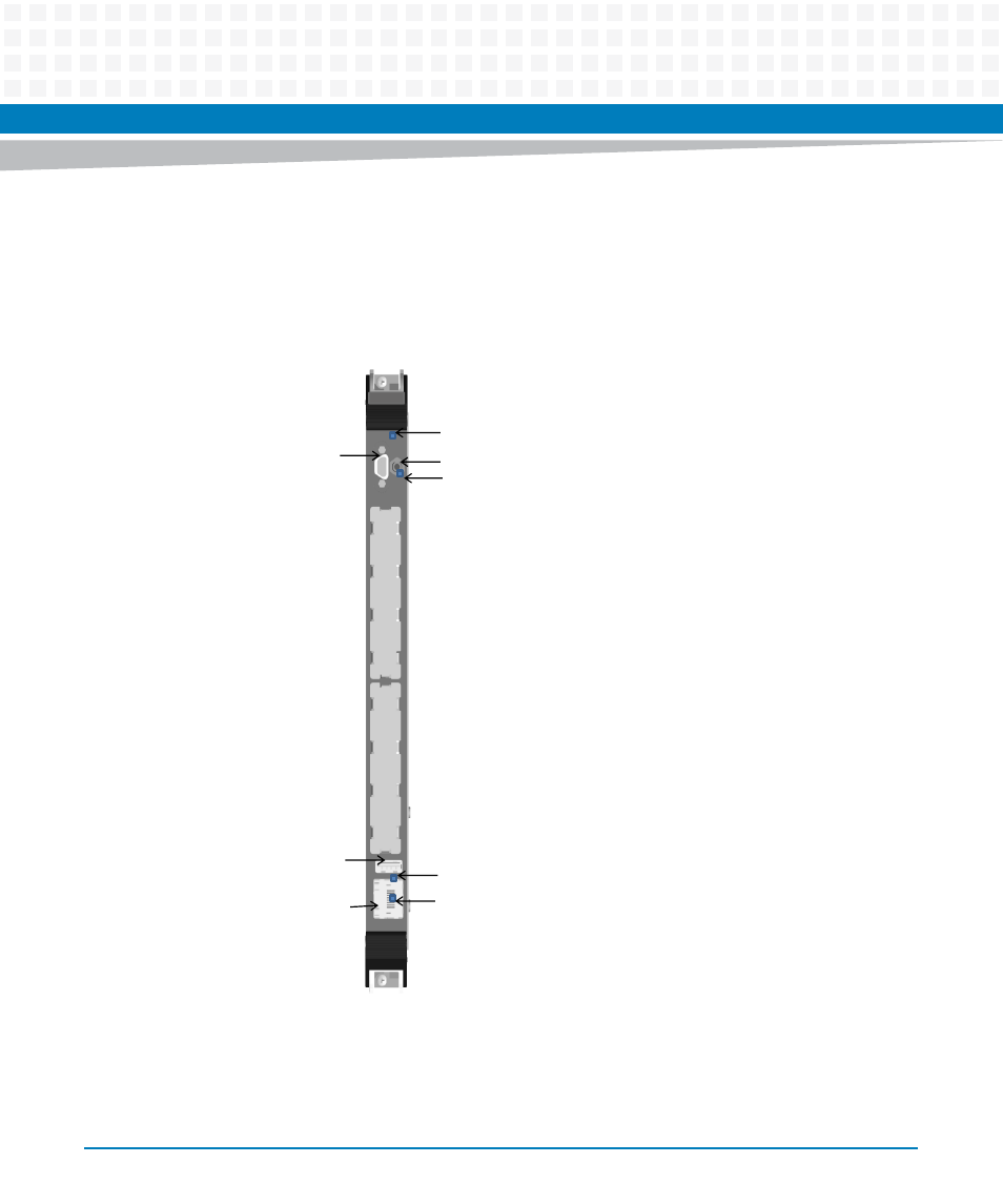
Front Panel
The following switch, LEDs, and connectors are available on the MVME8100 / MVME8110 front
panel. Refer to
for the location of each.
Figure 3-1
ENP1 Board Front Panel LEDs, Connectors, Switch
Console Port
Micro-DB9
Reset Switch
USB
2.0
Activity LED
Link LED
Board
Fail LED
User
LED
Gigabit Ethernet
Port
Advertising
This manual is related to the following products: