2 connectors, 1 external connectors, Table 3-2 – Artesyn MVME8100/MVME8110 Installation and Use (September 2014) User Manual
Page 55: Console front panel connector (j1), Table 3-3, Front panel tri- speed ethernet connector (j1), Controls, leds, and connectors
Advertising
Controls, LEDs, and Connectors
MVME8100 / MVME8110 Installation and Use (6806800P25G)
55
3.2.2
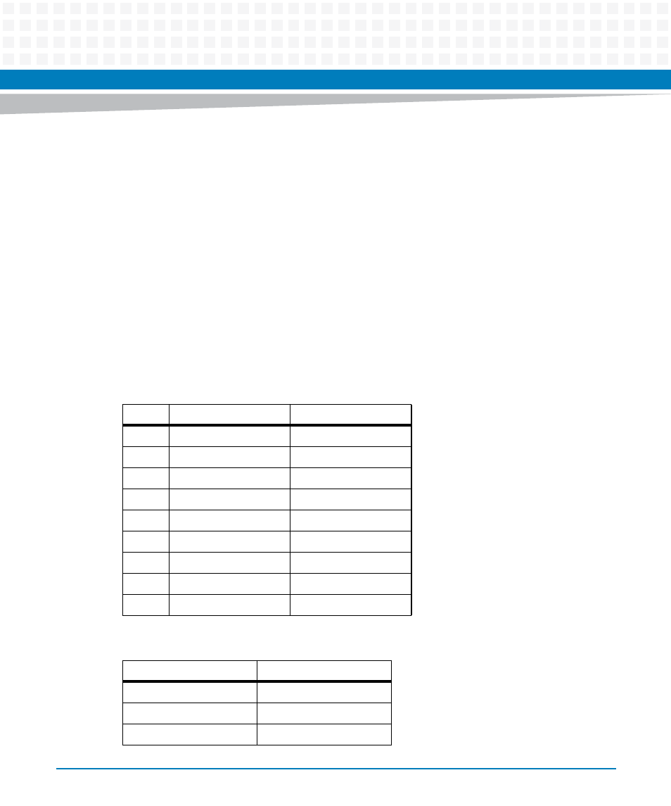
Connectors
This section describes the pin assignments and signals for the connectors on the MVME8100 /
MVME8110.
3.2.2.1
External Connectors
3.2.2.1.1 Front Panel Connectors
The following are the Front Panel Connectors:
Serial Console Port (J1)
Front Panel Ethernet Connector (J1)
USB Connector (J5)
Table 3-2 Console Front Panel Connector (J1)
PIN No
RS232 SIGNALING
RS485 SIGNALING
1
NC
NC
2
COM_0_RX
COM_0_RX-
3
COM_0_TX
COM_0_TX-
4
NC
NC
5
GND
GND
6
NC
NC
7
COM_0_RTS
COM0_TX+
8
COM_0_CTS
COM0_RX+
9
NC
NC
Table 3-3 Front Panel Tri- Speed Ethernet Connector (J1)
Pin No
Signal Description
1
TD0+
2
TD0-
3
TD1+
Advertising
This manual is related to the following products: