Insert optional equipment (continued) – Avalon Firestyles 796-1990 to 1993 User Manual
Page 30
Page 30
INSERT OPTIONAL EQUIPMENT (Continued)
1. Surround Panels (Continued)
INSULATION INSTALLATION INSTRUCTIONS
The installation of the insulation is required only for face seal connections. Direct and positive
connections do not require the insulation to be installed. Refer to the owner's manual for more details on
the type of installations available and the items that are required for each type of installation.
1.
With the insert drawn at least 6" away from the fireplace, glue the insulation strip included with the
surround panel kit to the back of the panels using RTV silicon or stove gasket cement. The insulation
should be installed so it overlaps the fireplace opening to form a seal between the panels and the
fireplace face.
2.
Push the insert into the fireplace, ensuring a seal is made with the insulation between the panels and
the fireplace face.
2. Surround Panel Brass Trim (Included with Surround Panels)
The brass trim kit is included with the surround panel kit and includes all of the items needed for
installation.
1.
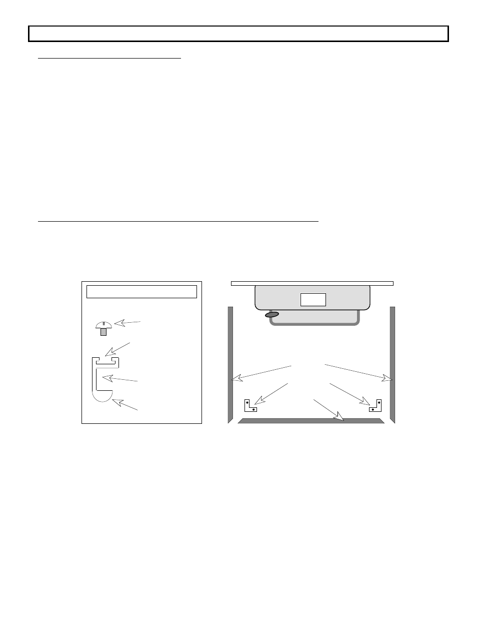
Lay the three pieces of brass trim on the floor in front of the insert. Arrange the brass trim so that it
resembles the illustration below. The rounded edge of the trim that will be facing outwards when
installed should be facing down.
"L" Brackets
Top Trim
Lay the trim on the floor in
front of the insert with the
rounded portion facing down.
Insert
Side Trim
"L" Bracket slides into
this groove
Surround Panels
slide into this
groove
Rounded portion
faces outward
when installed
Screw holds "L"
Bracket to Trim
CROSS SECTION OF BRASS TRIM
2.
Insert an "L" bracket leg into the groove in the 45
o
cut end of each side piece. Slide the other leg of
each "L" bracket into the groove in each end of the top piece.
3.
With a small screwdriver tighten the screws into the "L" brackets, ensuring that the 45
o
cuts are butted
together to form a neat joint.
4.
Lift the complete brass trim assembly and slide the side pieces down over the edge of the side panels
until the bottom edge of the brass trim is flush with the bottom of the side panels and the top panel is
in the groove of the top brass trim piece.